My Seeburg SC-1 Jukebox Consolette
restoration project as MP3 player
This project started some months ago
when I went to an antique shop
and found this little thing resting on
the floor,
in the dust, In a very bad state..
It reminded me my youth time having a
snack at some
snack bars and selecting songs on a
jukebox remote box
at the table’s edge..
The owner let it go for a fair price (to
me) so I went back home with it.
I knew something could be done out of
this unit
but I was wondering how..
then I thought this could
control a standard MP3 player that would
play the selected song.. Hmm..
I started to browse the internet for any
MP3 player
that I could use..
I order 3 different units that were deceiving.
In fact the most important thing was to
be able to play
the second or the 31st or 124th
song on the fly..
I finally found a very versatile player
called the Daisy board.
http://teuthis.com/daisy/index.html
The board is not cheap but it’s worth
its power.
It has different working modes to work
with but the one
I found the most powerful was the serial
mode.
So I decided to use that mode in my
code.
So for now talking to the MP3 board
would just be a question
of serial commands. I ordered the Daisy
board and
finally received it in kit form. Took me
some hours
to assemble it and it worked at the very
first time !
Back to the Seeburg Consolette now…
At home I started to investigate the
unit and sadly found
the side lock was badly hacked open with
an hand drill
that damaged some inside mechanics used
to keep
the metal front cover ‘secured’. One of
the metal front grid was
replaced somehow during the unit’s life.. both glass sides were broken
and had to be replaced and finally the 2
internal speakers were showing their ends of life.
But it was Ok to me because this little
jukebox remote
was worth it to me.
Figure 1 shows the original state the
SC-1 was in..
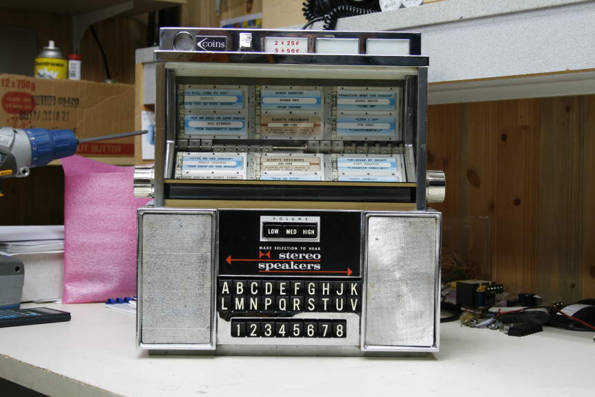
figure 1 -
Original Jukebox Seeburg SC-1 without modifications
So I first decided to replace both front
grids with original ones.
After some web browsing I found someone
who could sell me
these same type of grids and 2 original Seeburg speakers.
This person was Bill Butterfield at http://www.jukebox-parts.com/
waiting for the ordered parts I started
to ‘hack’ the inside of the beast..
I first started to remove the damaged
grids from the unit
and cleanup the metal housing.
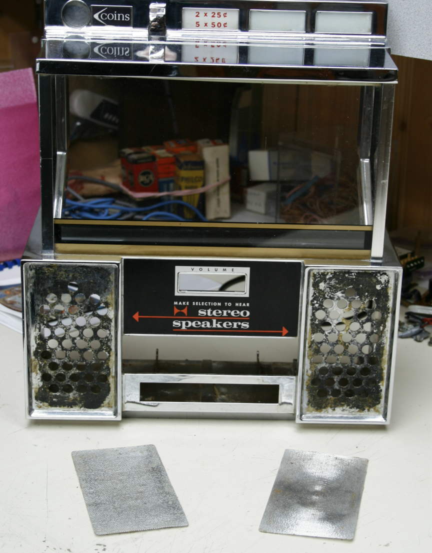
figure 2 -
Damaged grids removed to be replaced
So I removed the cabinet front and
investigated
the inside components. I chose what
would stay and what
would be unnecessary…
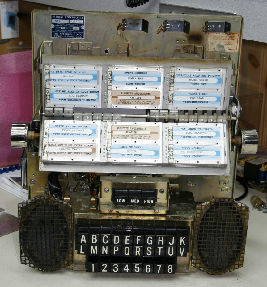
figure 3 -
Inside before any modifications
Figure 4 shows all the original parts
Dismantled and sorted. Those who were on
the bottom
were removed definitely.
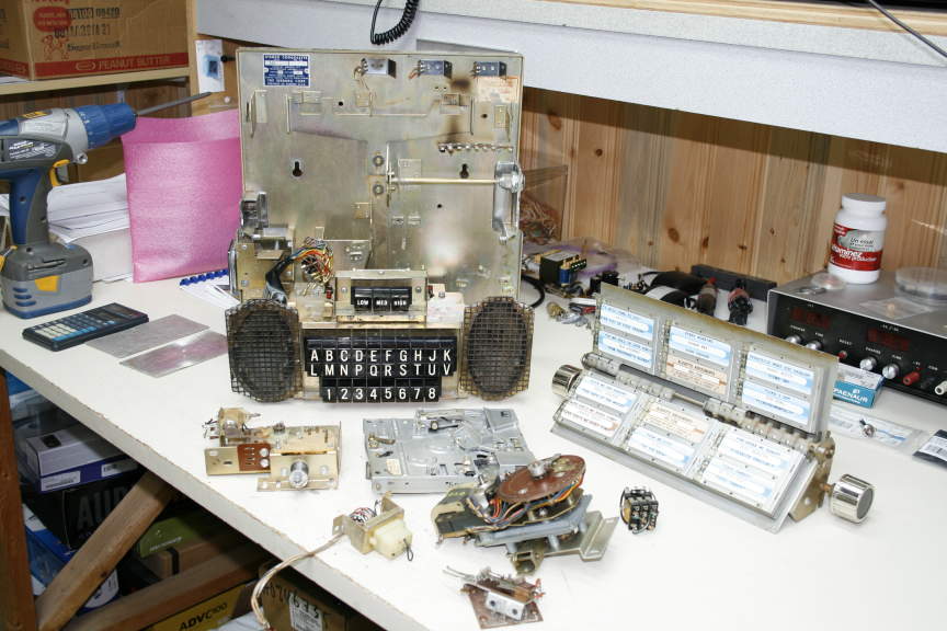
figure 4 - Some unnecesssary
parts removed…
Then my next job was to find out how the
push buttons
worked mechanic and electric wise.
Figures 5 to 7 show
some wiring details and color codes of
all the 3 rows buttons.
I discovered the push-buttons were
normally closed switches
all wired in series. By pushing one
button the switch chain opens up
and it’s then easy to read what button
was pushed by inserting
pullup resistors between each switches to the interface board’s Vcc.
( See the actual push-buttons wiring here )
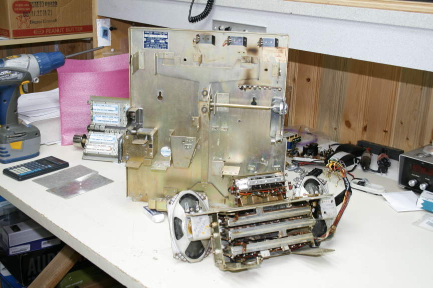
figure 5a - Push buttons unmodified back
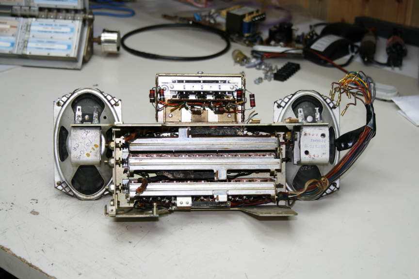
figure 5b - Push buttons unmodified
wirings details
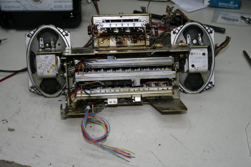
figure 6 - Push buttons wires
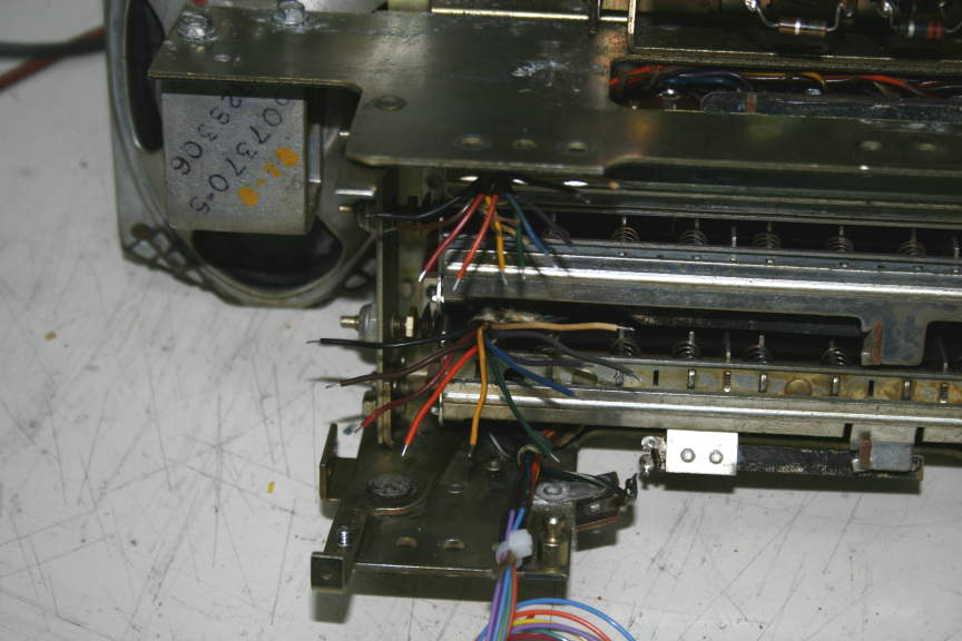
figure 7 - Push buttons wires color code
details
Then I discovered I had removed an
important mechanical
component that served to ‘unlatch’ a
pair of pushed buttons
to accept a next song selection…. oops
!!!!
So I had to figure out the behaviour of
all the push-button
housing and mechanical latches before my
removals. It was a bit tedious but
I found what was the sensible part of
the latches to take care of.
So I placed a solenoid activated by the
Interface board
That would ‘pull’ the buttons mechanism
to unlatch them.
The first 2 rows (letters A to K and L
to V) had a different
part to pull from the 3rd row
(1 to 8) so I had to link all the 3 rows
to unlatch them all together.
See Figure 8 for solenoid assembly
details.
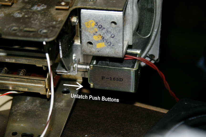
figure 8 – Push buttons unlatch solenoid
installation details
I then started to write C code for the
PIC16F877
that would be used in the Interface PCB.
The complete C Code files written in HiTECH C are available here.
I first wrote the push-buttons
deciphering code.
The one who actually ‘reads’ what switch
pair was pushed
and decode what song number would be
called to the MP3 player board.
The 3 rows give a possibility of 160 songs !
After some days of calculations and work
the switches were read correctly so I
could
start the code to actually ‘talk’ to the
MP3 player.
I knew I would need a stereo amplifier
strong enough
to drive the internal speaker (and
usefully better external speakers).
Because I live in Quebec City, Canada I
checked for a near electronic
kits seller that would have a stereo
amplifier not expensive
and strong enough for what I needed and
I found a company
called CANAKIT http://www.canakit.com
That had the perfect kit for me.
http://www.canakit.com/10w-stereo-audio-amplifier-kit-ck154-uk154.html
A 10watts stereo amplifier not expensive
at all.
I bought it in Quebec City and wired it
to the MP3 player.
See Figures 9 & 10 for my tests
assembly.
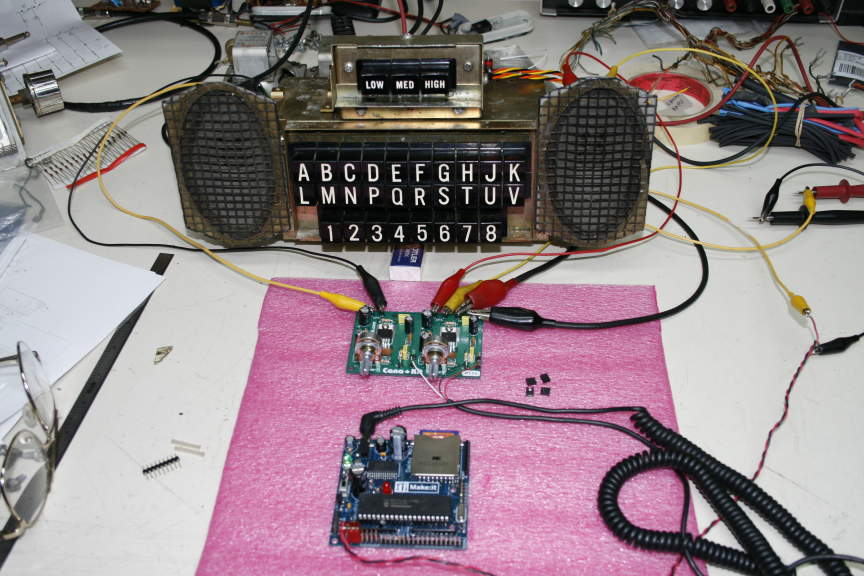
figure 9 – Daisy MP3 player and amplifier
first tests
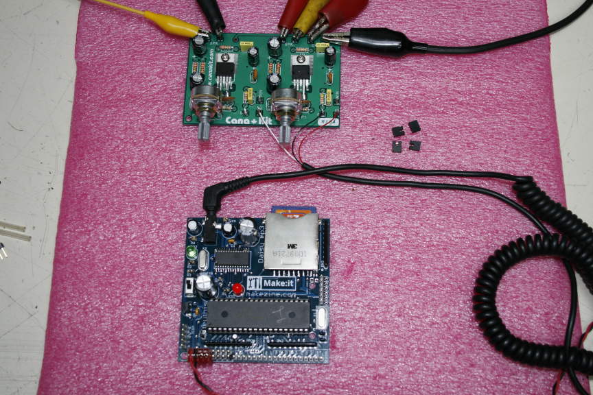
figure 10 – Daisy MP3 player and amplifier
details
When I finished my Interface C code I
started to
draw the actual schematic and PCB to be
used inside the jukebox.
Here are the schematic
and the PCB.
I tried to hold most of the PCboards in place using the available screw holes
Already punched on the back plate of the
Consolette and spacers.
See figure 11 showing the chosen
mounting holes for the Interface.
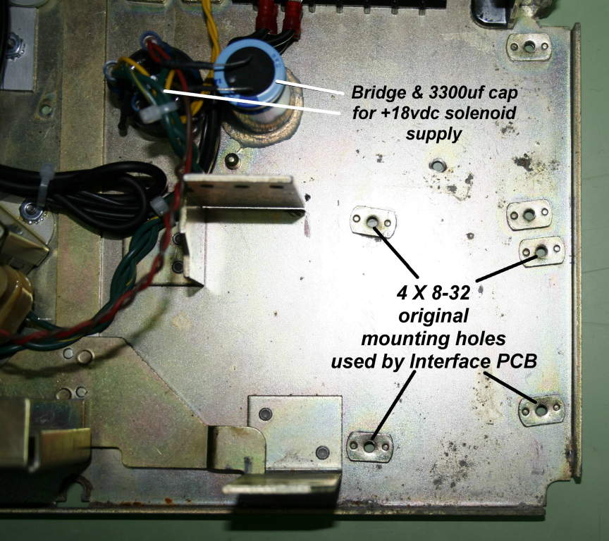
figure 11 – Consolette back plate mounting
holes to use
Now the fun began!
I mounted all my boards the best I could
with the least space used on the back
metal panel
using plastic spacers and ½” 8-32
screws.
See Figures 12 to 16 for all assembly details..
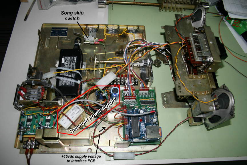
figure 12 – All the parts screwed &
wired inside
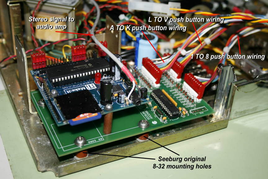
figure 13 – Daisy board on top of
interface board
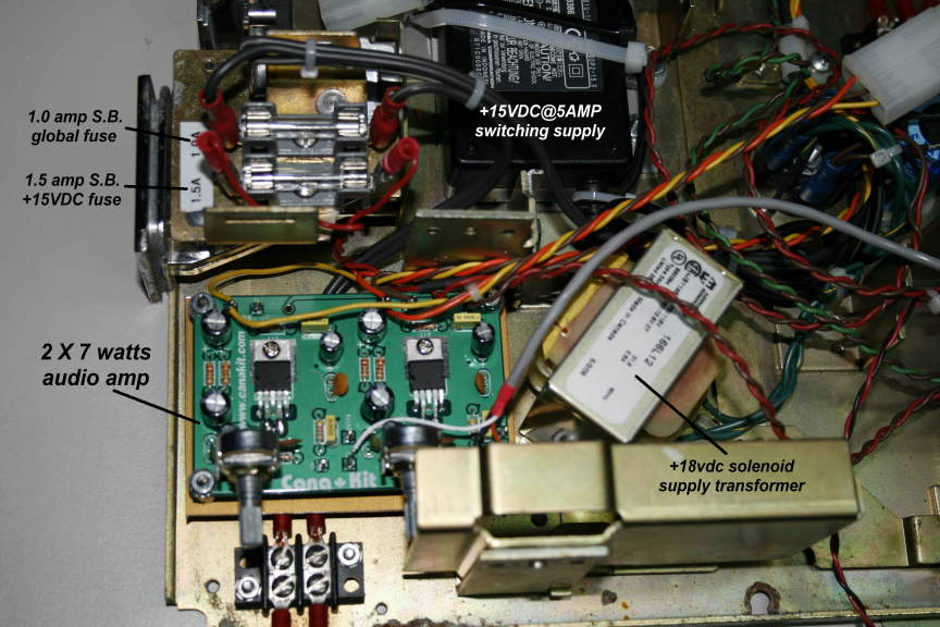
figure 14 – 2 X 7 watts amplifier wirings
& switching power supply
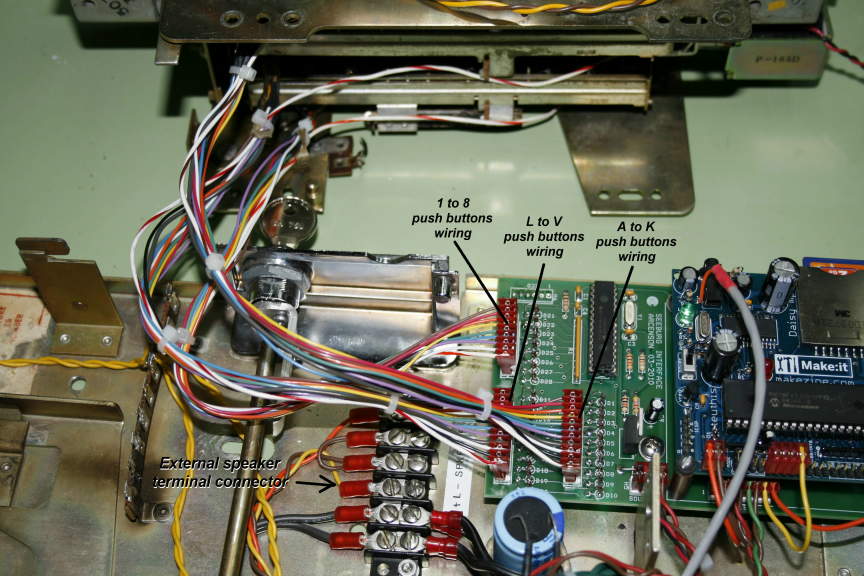
figure 15 – Push buttons wirings to
interface
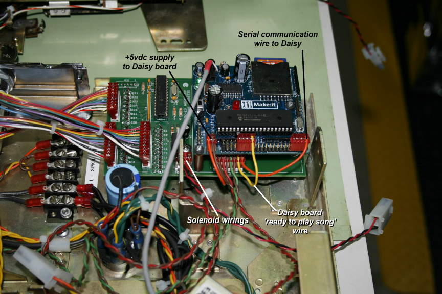
figure 16 – Wirings between Daisy board
& interface
My C code includes a ‘SKIP SONG’ rocker
switch option
whenever the user wishes to skip a song
for whatever reason
so, I placed a momentary, normally open
switch on top
of the jukebox back plate, placed right
below where
the ‘Money Change’ key goes down
whenever pushed down.
See Figure 17 for more info.
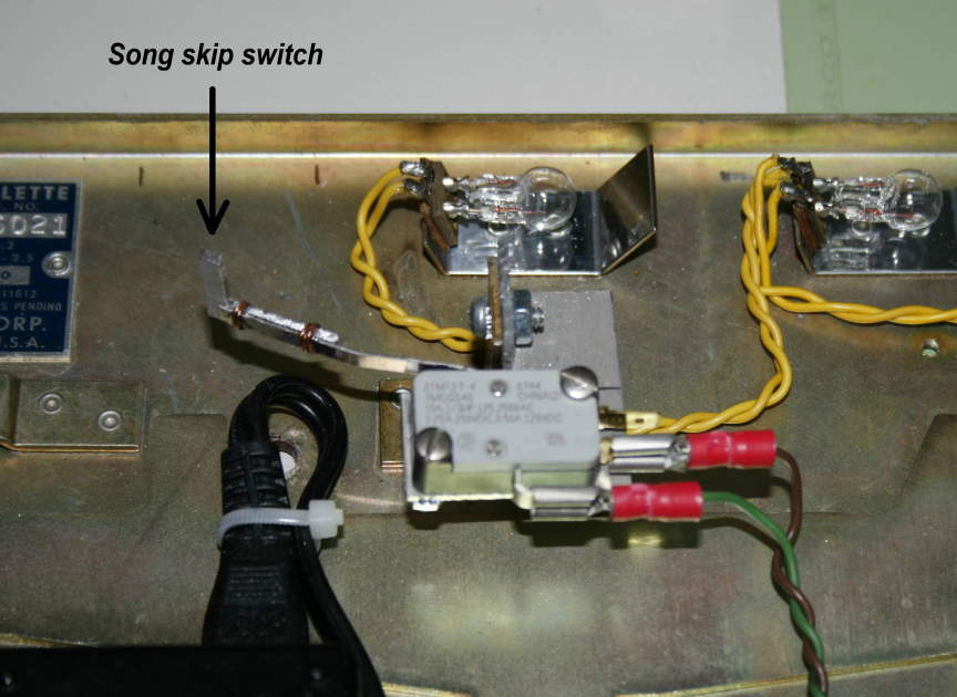
figure 17 – Song SKIP switch hardware
details
After the software side and hardware
assembly were done
I continued restoring the damaged parts
of the SC-1.
I first chose all my 160 songs selection.
They needed to be named starting like
00001xxx.MP3
to 000160xxx.MP3 to be used correctly
with the Daisy serial song read convention.
Then I scanned and downloaded some available
empty color labels
to print my songs/Artist names on.
Then I removed the worn Song label’s
side numbers
and replaced them with newly made ones…
Figure 18 shows before and after
restoration.
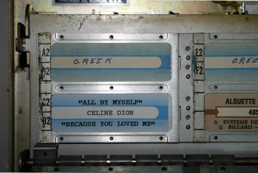
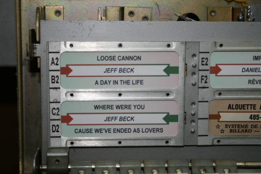
figure 18 – Songs labels before and after
restoration
And the complete and final restored SC-1
Seeburg Consolette.
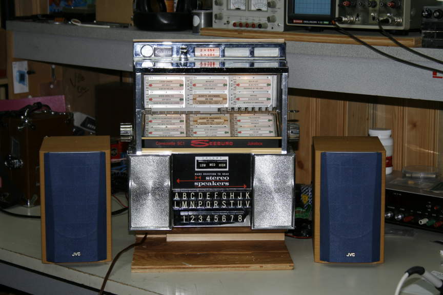
figure 19 – Seeburg SC-1 Consolette
finished restoration
This is my setup mess during all my
prototype phase..
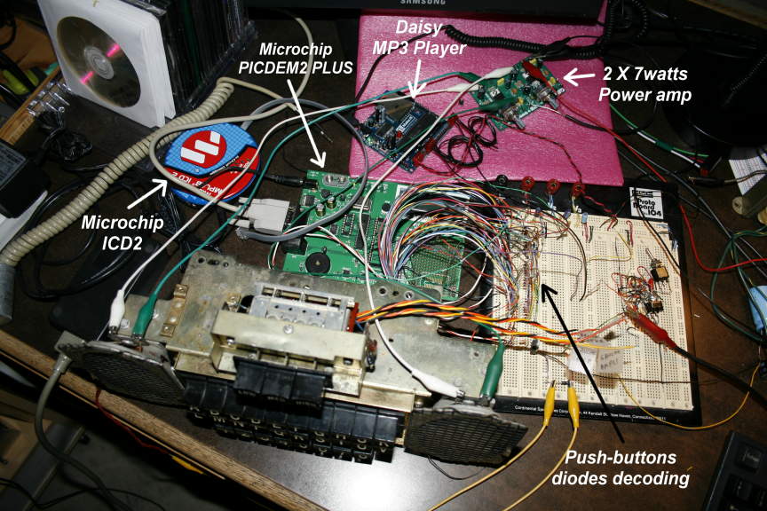
figure 20 – Prototype time…
So that’s it !
Thanks for watching and feel free to ask
any questions
about this project using the email
below. By the way I have some Interface PCB’s left
that I could let go for cheap.
If you’d
like to have a look at some of my other projects
Just
go to www.arcenson.com/projects

info@arcenson.com
2010