My MIDI Piano Roll Player project
This project started some years ago when
I heard a player piano playing
A very old song from a small roll of
paper.
I already knew these special pianos but never saw one clearly
sitting close to me. So, I started to have a look inside
the small opening window showing the paper roll
to ‘see’ a small part of its inner mechanism...
So, I started to read and learn about
how these pianos worked
And found a very complex machine... more
complex than
I ever expected.
I said to me Why not play these paper rolls real-time with a stand
alone
micro-processor driven device?
So I started to browse the internet for
any project
that would have been done with mostly the same goal as mine ..
And I found a guy who actually thought about an optical way
to read the piano paper holes instead of using pneumatics
like the original mechanical piano did in the past (and still today).
It used a large row of Infrared LEDS placed in front of the scrolling paper
and around 88 photo-transistors placed inside the brass tracker bar
adjacent holes. It said it chose to use Infrared LEDs instead of
visible colour LEDs because the visible light could actually
go across paper more easily than IR light.
For IR light, paper is like a concrete wall!
And the ambient visible light over the paper could affect
a good and effective reading of scrolling holes.
Unfortunately, its web page with its
project disappeared over time
and I couldn’t go along with what its project came out as a final result...
So…
I had to figure out all the rest by
myself. Good and Challenging!
Ok. First, I had to find a complete
working piano mechanism
to start my project. So, I contacted some piano repairmen and asked
for any remaining mechanism I could salvage for free...
I found a kind repairman who said he
often has these mechanisms
that owners want ‘expelled’ from there pianos.
Sometimes it keeps parts of them, sometimes dumps them in containers!!!!!
Brutal phrase to hear...
Any way I manage to get one mechanism in
very good condition.
Huge thing to bring home... Here are some images of this beast...
The original Beast...
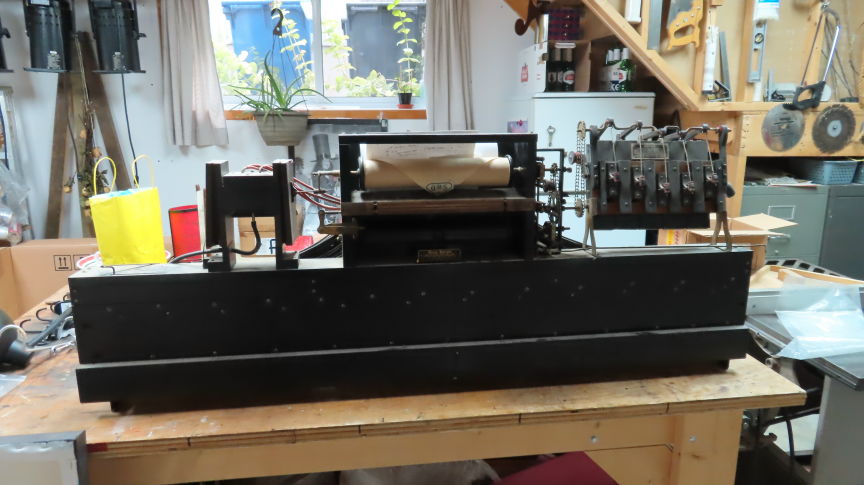
figure 1 – The
complete pneumatics mechanism - front
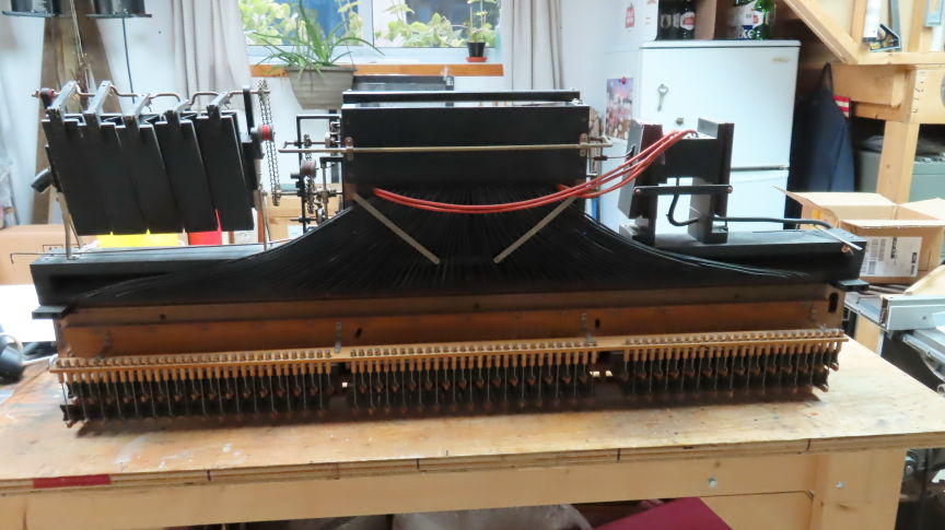
figure 2 – The
complete pneumatics mechanism - back
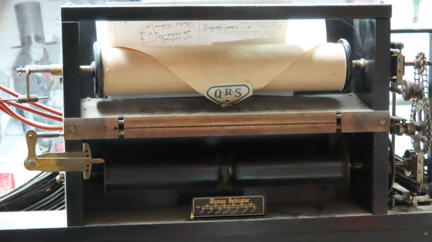
figure 3– The
main central paper scrolling unit
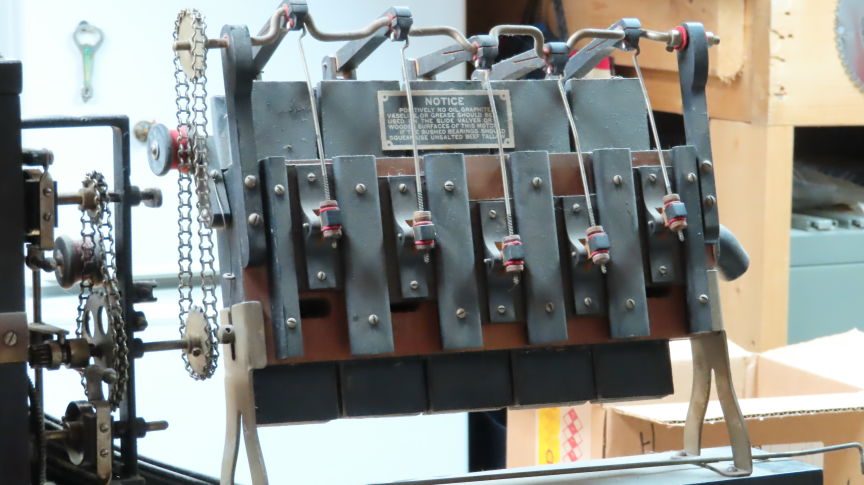
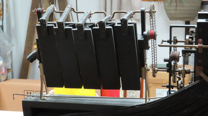
figure 4 – The
pneumatic rotating section (5 bellows powered)
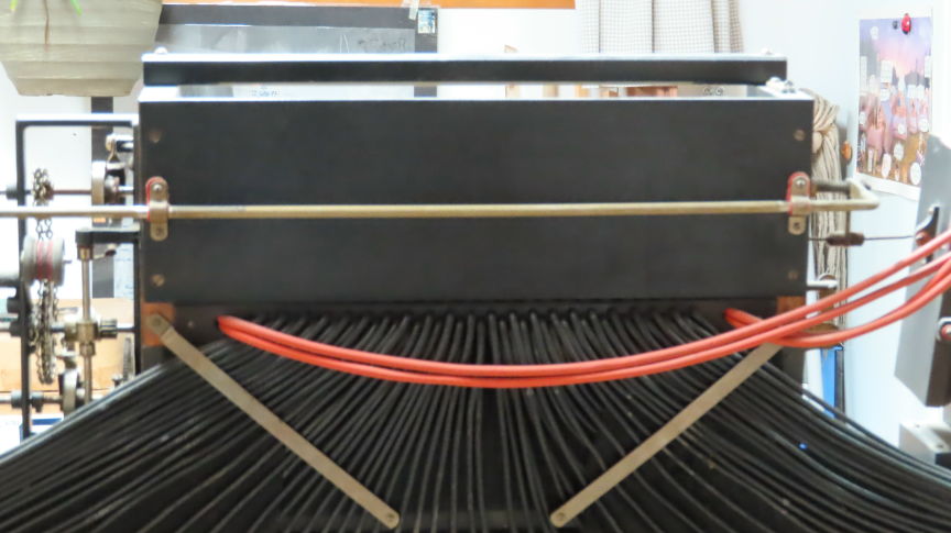
figure 5 – The
90 original lead pipes reading vacuum paper holes.
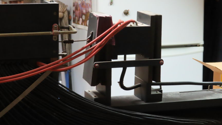
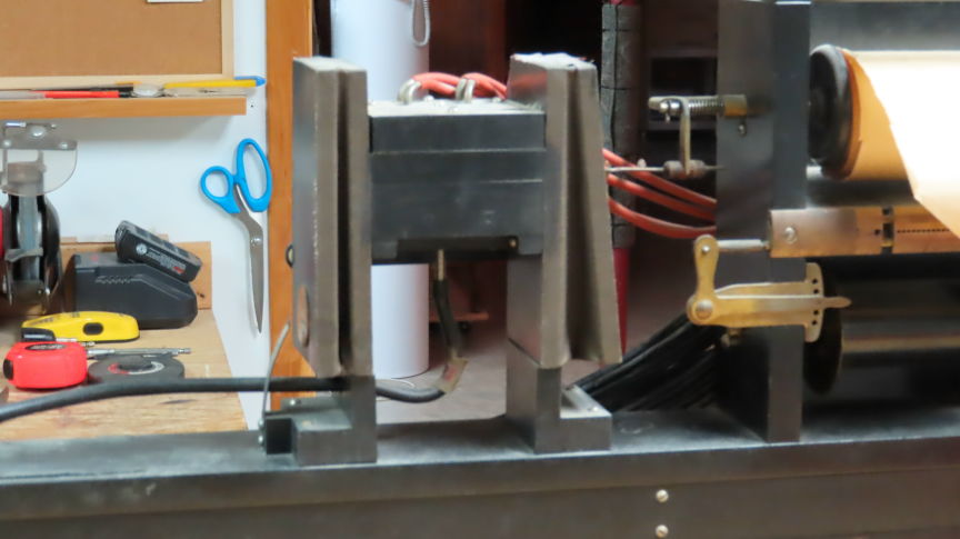
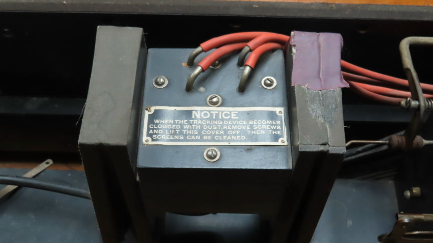
figure 6 - The
original 2 bellows paper auto-centering reading 4 ‘tracking’ holes
Steps involved in this project:
1. Remove
all the pneumatics related parts
2. Remove
all the tracker bar’s lead pipes and clean all its 91 square holes
3. Clean
the brass tracking bar & offset adjustment
4. Design
a main PC board to do all the needed job
5. Write
and compile a prototype software to test all the new parts
6. Install
new 12VDC and 24VDC power supplies
7. Install
both scrolling and centering step motors
8. Testing
both motor’s torque
9. Install
a PLAY/REWIND actuator on front panel
10. Adjusting
scroll motor speeds by standards (software)
11. Make
1,2,3….13 feet marks on test paper roll for speeds adjustment
12. Write
software for paper scroll step motor speed & BPM meter
13. Install
new front BPM indicator using green LEDs
14. Install
all the 91 optical sensors with light pipes
15. Test
all the 91 optical sensor’s gains and accuracy (voltmeter)
16. Test
the 91 optical sensor’s digital reading accuracy (without jitters)
17. Dotted
type lines of long duration notes... how to read them
18. Figuring
out and finalize paper auto-centering mechanism
19. Testing
paper auto-centering mechanism while listening notes (software)
20. Install
MIDI output cable between main PCB and MIDI piano sounds module
21. The
2 x 20 watts power amplifier
*** Remove all the pneumatics
related parts ***
Removing the original lead pipes...
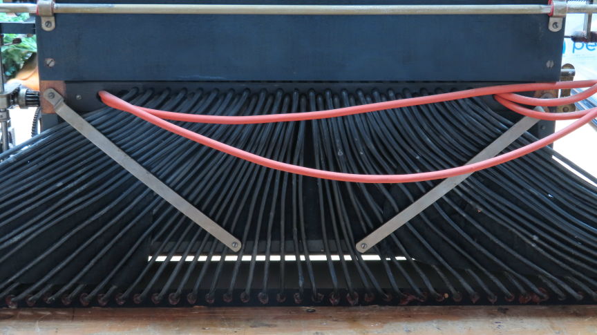
figure 7 – The
original lead pipes before removing...
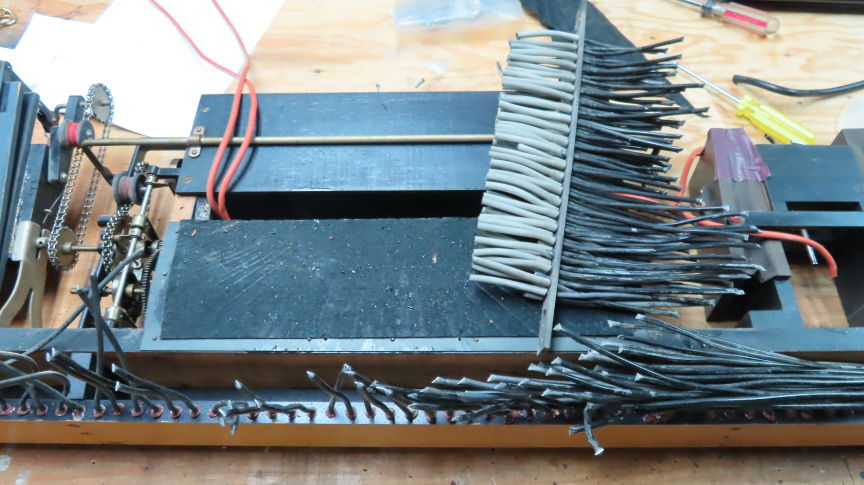
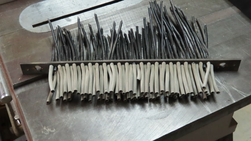
figure 8 – The dried-out lead pipes
breaking on removal...
Figure 8 left shows how the original
lead + rubber pipes were
very dried out and breaking on removal of the brass tracker bar.
The dried-out rubber parts of the pipes
are the light grey ones.
A card board band was used to align all the 90 pipes
to the brass tracker bar. We can see the remaining lead portion
of the pipes on the upper section of the right picture.
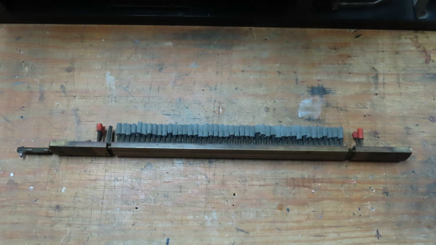
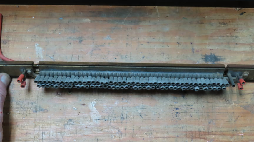
figure 9 – What is left on the tracker bar
back side
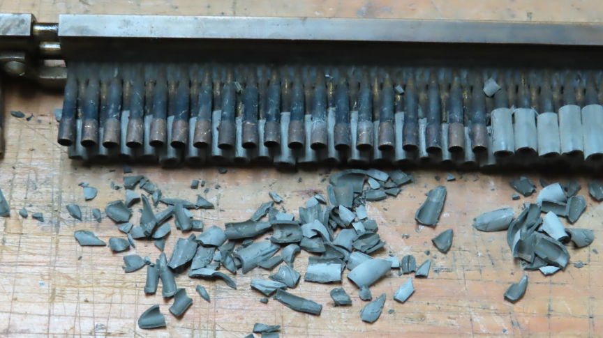
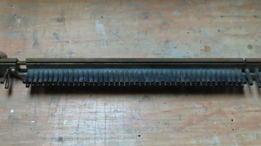
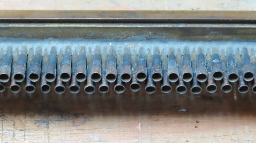
figure 10 –
Removing what’s left of the rubber end tied to the tracker bar
On figure 10 we can see how much brittle
the rubbers were...
Bottom picture shows all the ‘almost cleaned up’ 91 tracker bar’s back brass
pipes
tied to their respective 91 aligned front holes.
*** Clean the brass tracking
bar & offset adjustment ***
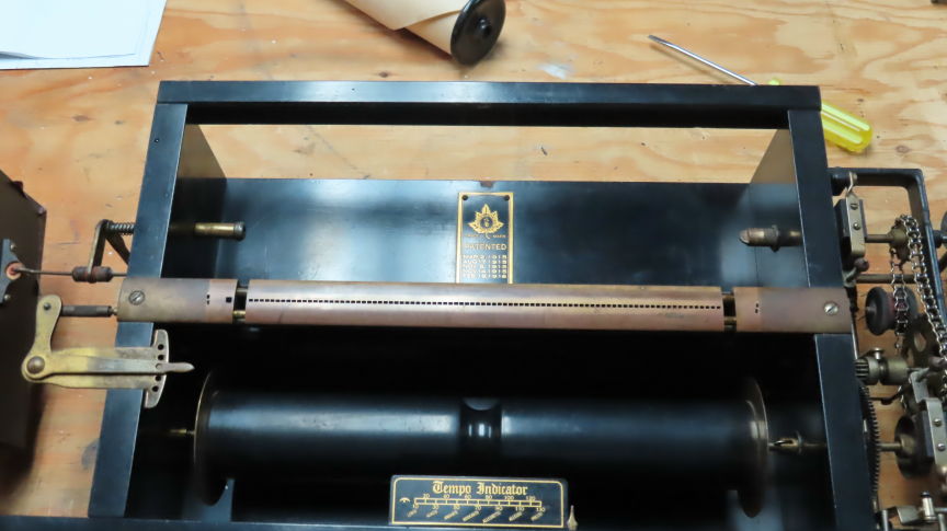
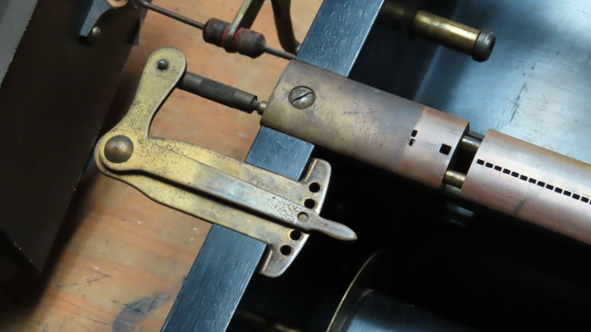
figure 11 –
Brass tracker bar & offset adjust before cleanup
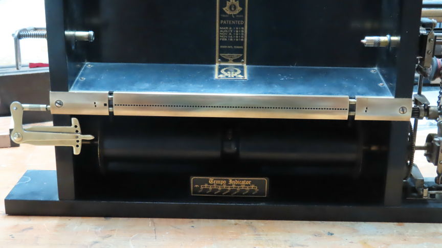
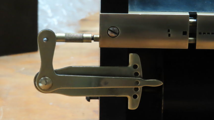
figure 12 –
Brass tracker bar & offset adjust after cleanup
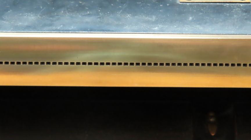
figure 13 –
Details of some of the 91 brass tracker bar square holes
*** Design a main PC board to
do all the needed job ***
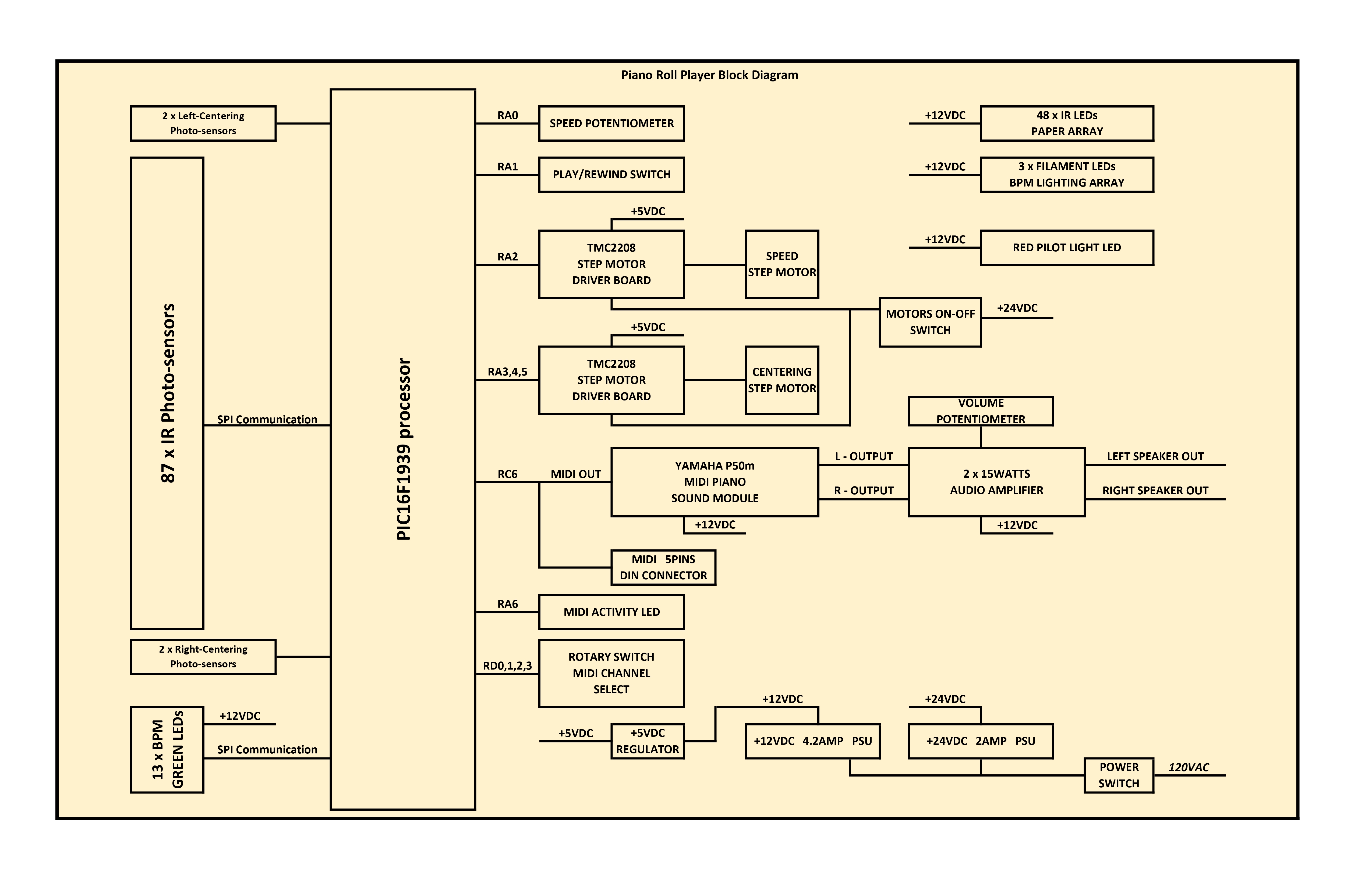
figure 14 – A
Complete Block Diagram of the project
Here are some of the project’s
schematics and PCB’s
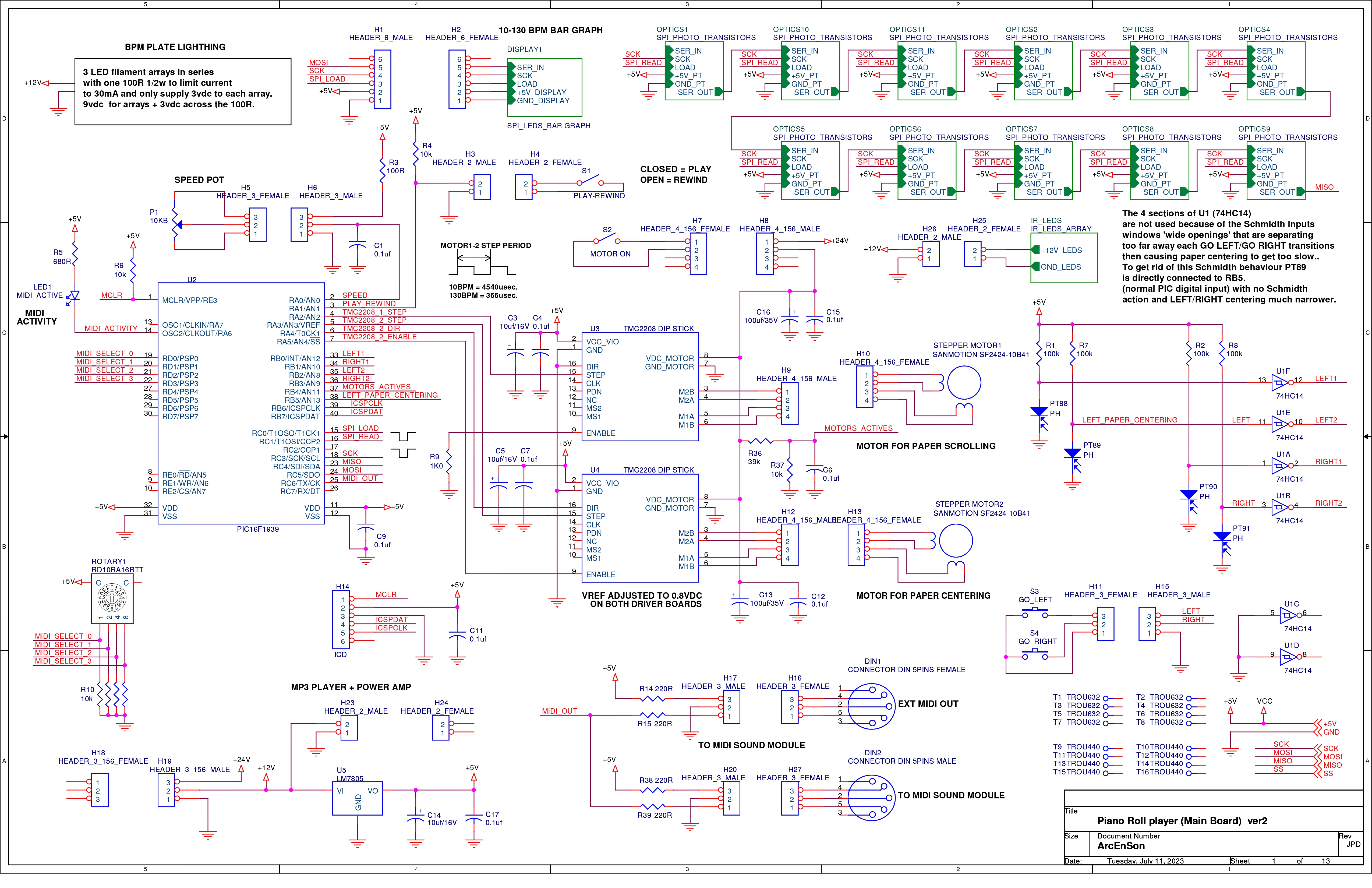
figure 15 –
Main micro-processor board with peripherals
![]()
figure 16 – One
of the 11 parallel to SPI converters (photo-transistors readings)
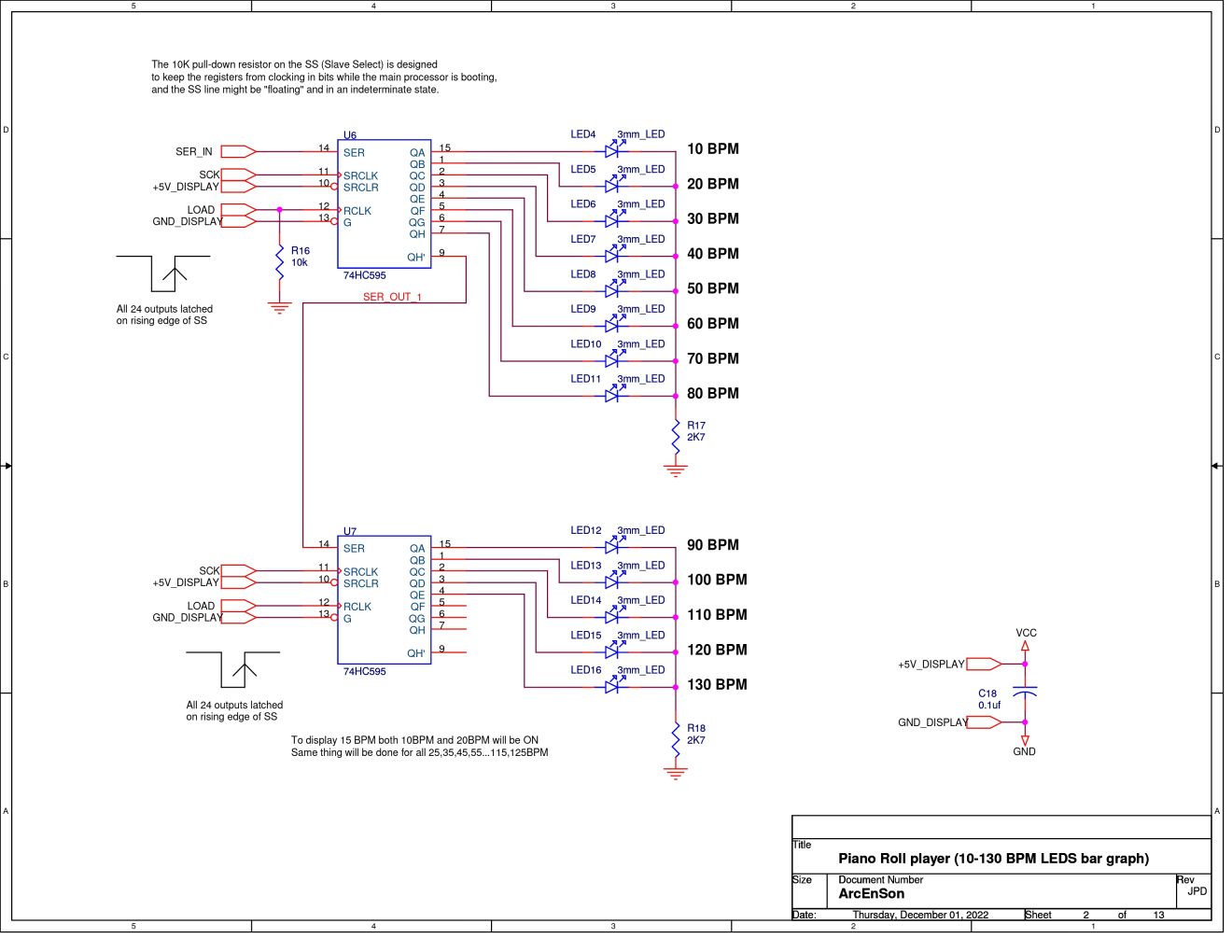
figure 17 – The
two SPI to parallel converters (BPM green LEDs)
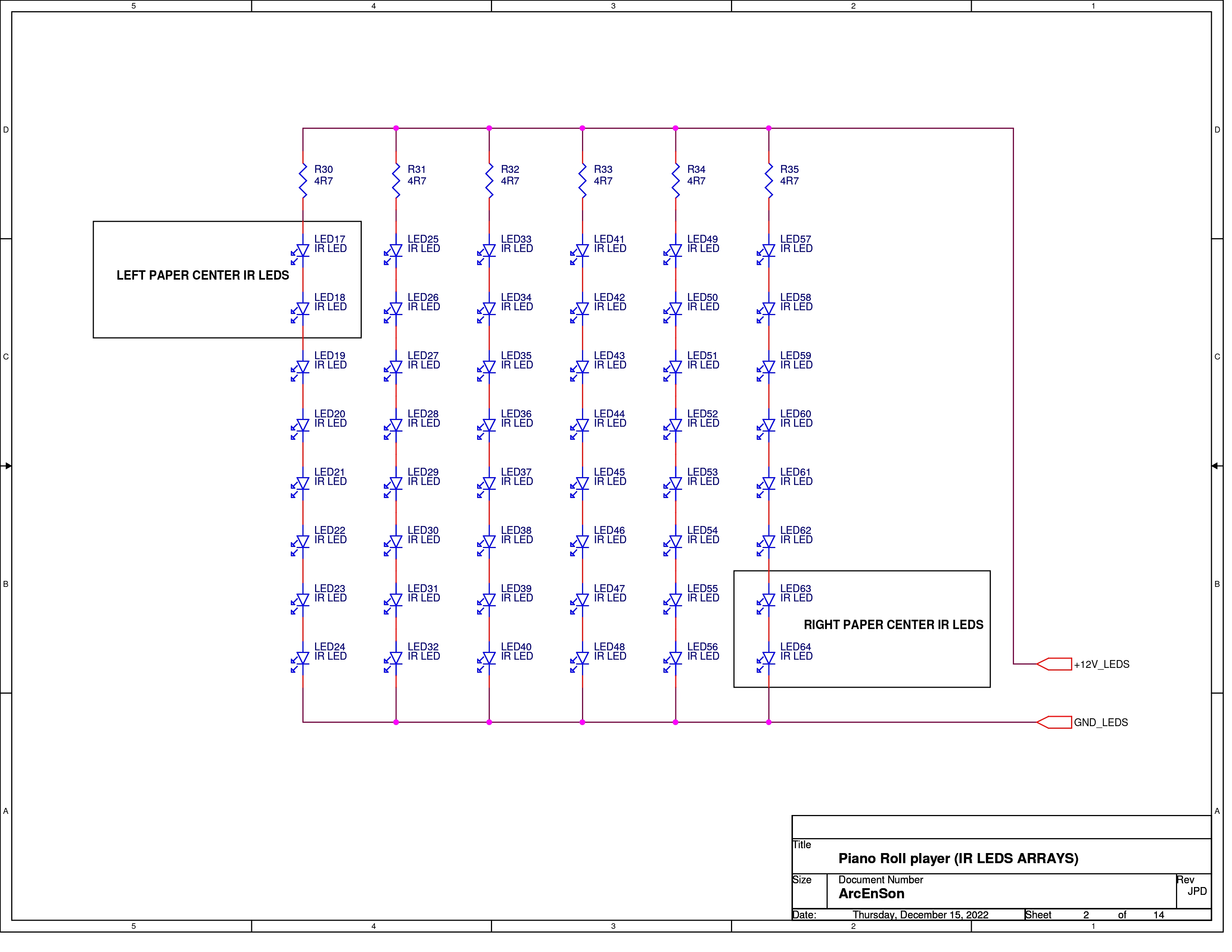
figure 18 – 48 x IR emitter LEDs array
mounted on liftable hinge
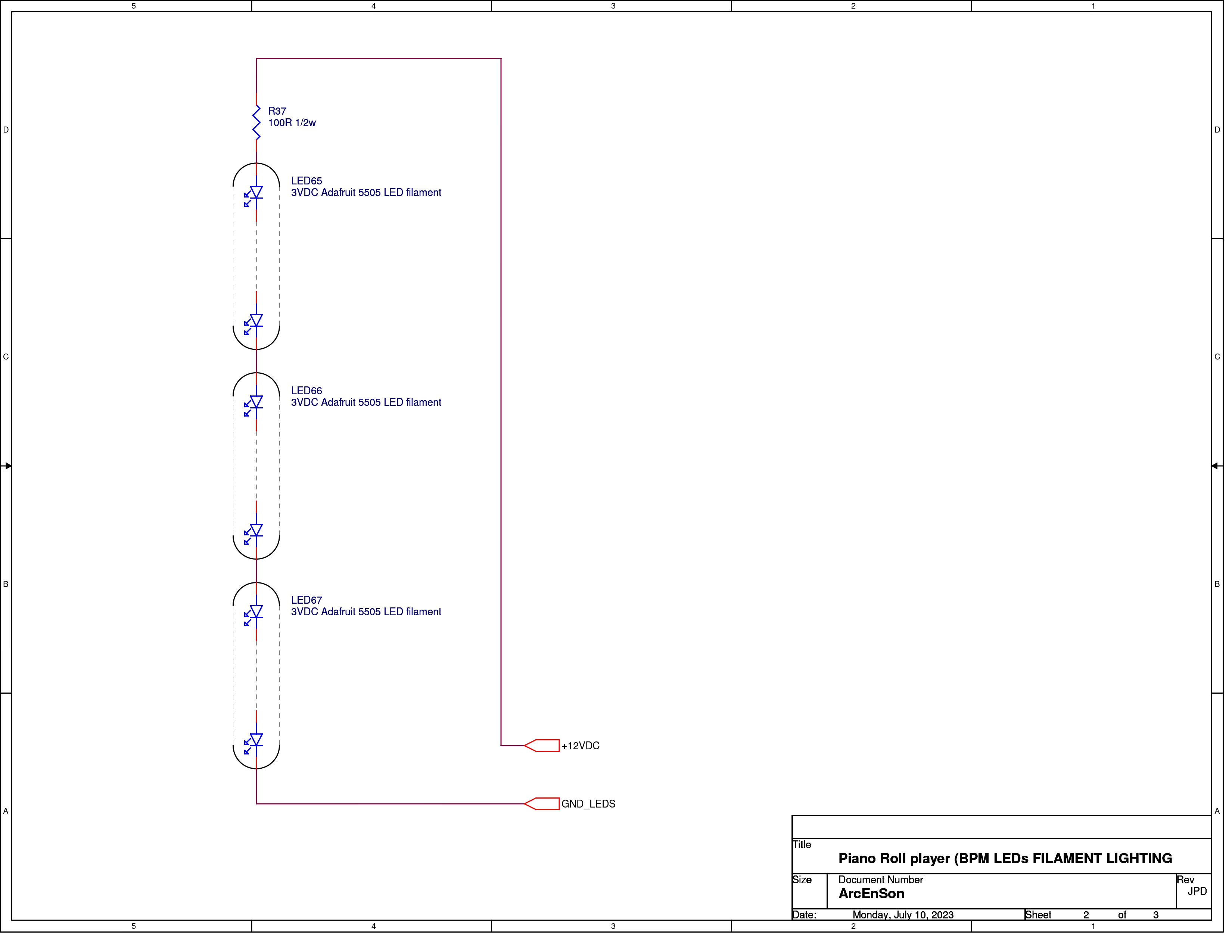
figure 19 – The
three Adafruit 5505 Filament LEDs arrays circuit

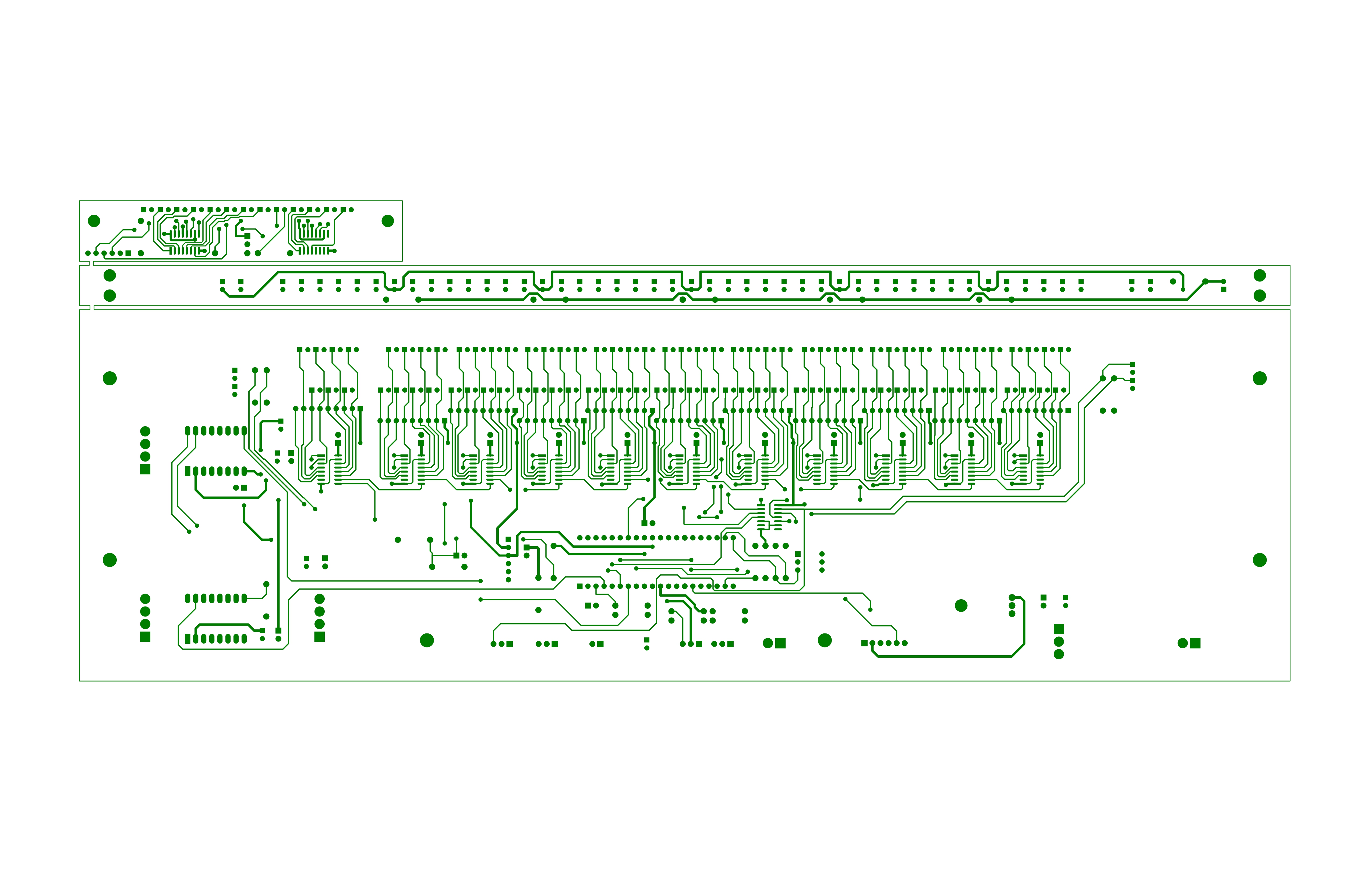
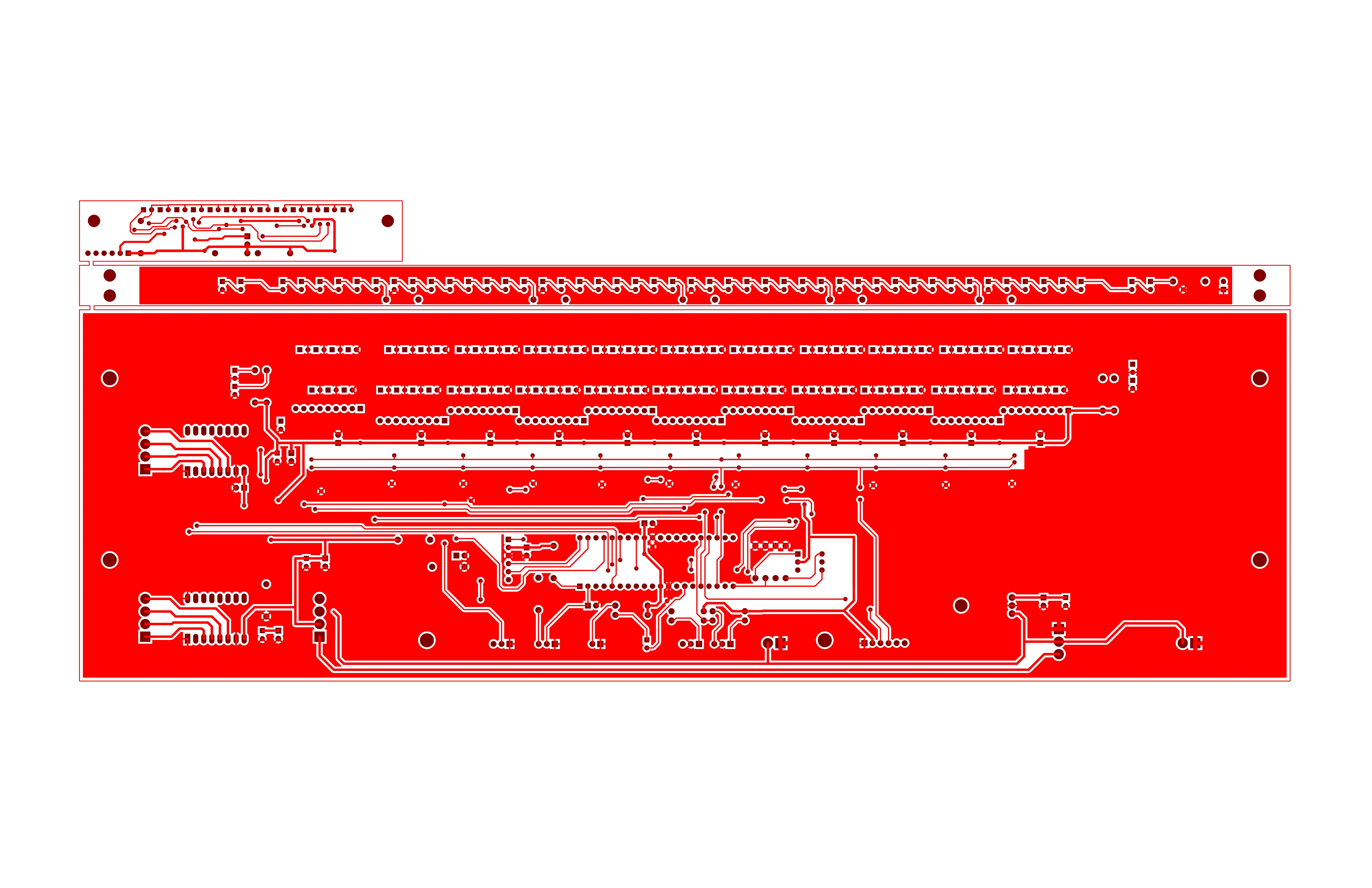
figure 20 – The
main PCBoard with IR LED emitters array and small BPM
display board
*** Write and compile a
prototype software for tests ***
All the C code for this project has been
made using Microchip
MPLAB X IDE v5.45 environment. The Micro-controller is a PIC16F1939.
All the detailed source code can be found HERE.
*** New 12VDC and 24VDC power
supplies installation ***
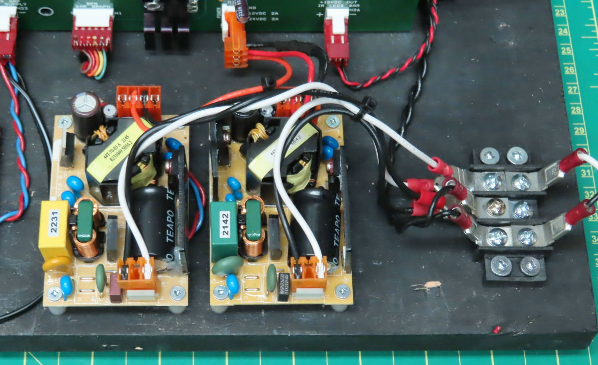
figure 21 – On
the left 12VDC, on the right 24VDC supplies
The 24VDC @ 2.2A power supply is for both
stepper motors and
for the BPM bright white array of LEDs. The 12VDC @ 4.5A supply is used
for the 48 x IR LEDs emitters array including the
Wave Trigger sampler board, The 2 x 20W audio amplifier and the front LED pilot
light.
*** Scrolling and centering
stepper motors installation ***
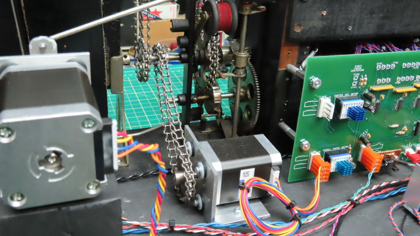
figure 22 – On
the left the paper centering stepper, on the right the scrolling stepper motor
When I started this project, I knew I’d need motors
to run all this machine. I first thought about using DC motors
but these motors would not keep accurately their speed and would
need time to start AND to stop every time they would be powered.
Even with servo control they would also need speed
reduction gears...
So… Why not use stepper motors? They start & stop very fast and are very
precise
on their speed. The only drawback is their torque at high speed.
Well high speed would not be an issue here. I first chose the following stepper motor
A 12VDC Adafruit 324 stepper motor. At 200 steps full rotation
(1.8deg steps)
*** Testing both motor’s
torque ***
The precision was Ok but after some testing’s I found this stepper would not
have
enough torque at max speed on paper scroll. At some points the paper would stop
scrolling...
So, I looked at the other NEMA steppers and found a 200
steps stepper running at 24VDC.
This new stepper was around 5 times stronger than the Adafruit 324 series.
This stepper motor is the SANMOTION
SF2424-10B41
The choice for good stepper motors was now done.
But I faced a new problem... NOISE !
When these stepper motor were directly driven by ‘H’ power transistors
drivers you could hear ALL the steps ‘banging’ one after the others..
Very annoying and not admissible in my type of ‘musical’ project.
So I started to make more readings and found that CRC routers
that uses many stepper motors mainly use some kind of ‘quiet’
intelligent stepper motor driver boards. And these small driver boards are
cheap!
Introducing the TMC2208 -SilentStepStick board.
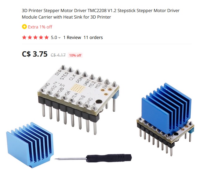
figure 23 – TMC2208 stepper motor silent driver
After sticking the top heatsink to this small board, wiring it
between the micro I/O pins
and the stepper coils and tweaking its coil current BIAS trimmer
following the PDF instruction
I found it amazing how quiet the stepper motors were now !!
See the previous main schematic for how the wiring to the PIC16 was made.
*** PLAY/REWIND actuator on
front panel installation ***
The installed scrolling motor
installation will now need a PLAY/REWIND
actuator to make the paper travel direction job easier. The original direction
changer
was made of a steel rod that would go to far the right side of the keyboard
and actuated by the player manually. I decided to use the same rod but make it
shorter
to be used on my controls front panel. The 4 pictures on Figure 24 show the
setup.
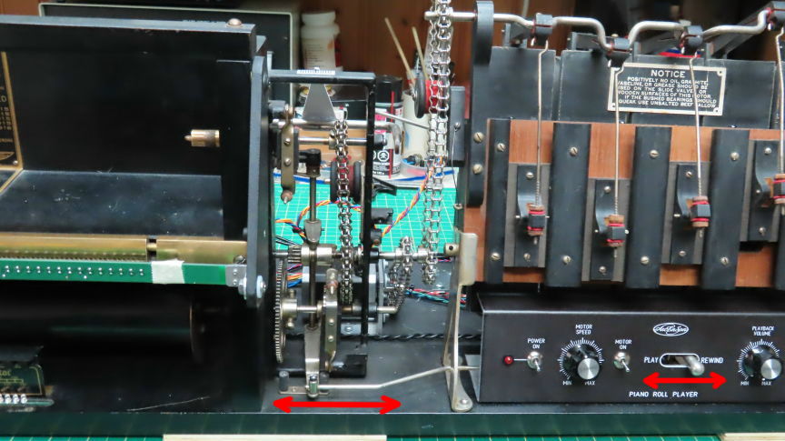
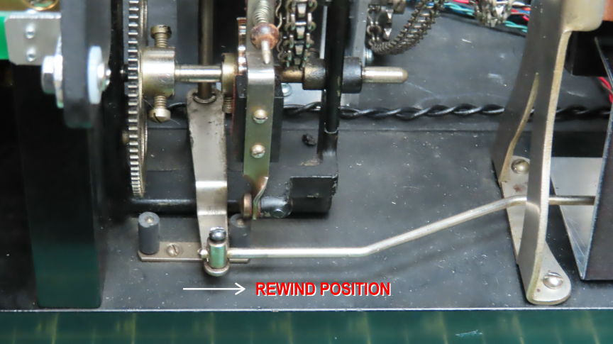
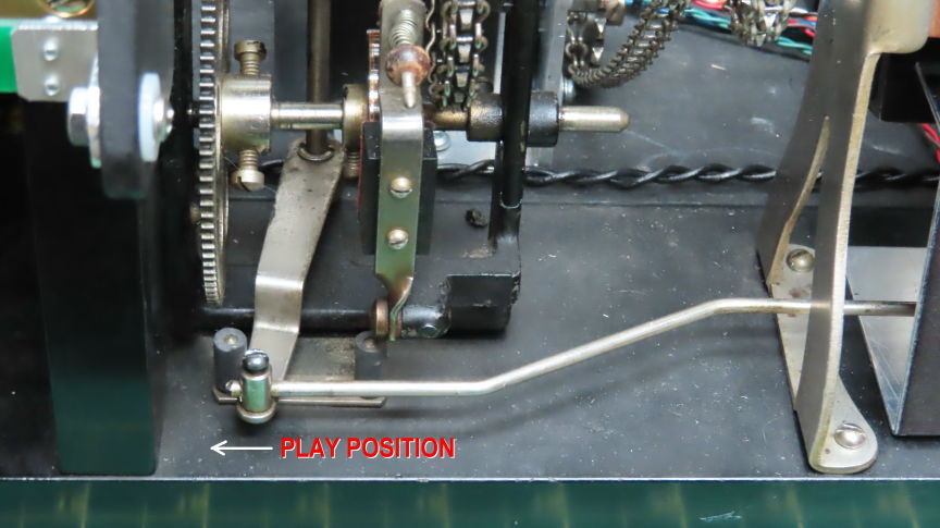
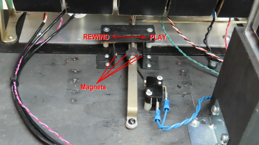
figure 24 –
PLAY/REWIND actuator mechanism
The last picture in figure 24 shows the
use of 4 magnets that made sure the direction lever’s position
would keep its ‘blocked’ position and stay engaged. A proximity switch makes
the interface
with one of the micro-controller I/O pins and makes it
change the scrolling motor direction
accordingly. This is done by changing the ‘direction’ pin signal HI or LO
on the TMC2208 - SilentStepStick board (explained
below) who drives the scrolling motor.
*** Adjusting scroll motor’s
speeds by standards (software) ***
Paper speed standards for player piano are made around units called BPM
or ‘Beat per minute’. So, I need to implement
some kind of software driven pulses to drive the scroll motor
to achieve the needed speeds manually from a ‘step programmed’ potentiometer
placed at the front panel with other controls. The scrolling paper length
will be a fast and precise way to calculate the software’s variables.
To make things easier I first worked on
the paper scrolling stepper.
The paper centering stepper could wait a little later...
*** Make 1,2,3…. 13-foot marks
on test paper roll for speeds adjustments ***
To get the good MIN/MAX speed needed for the scrolling paper I needed
to check for the player piano roll speed standards which stated:
the minimum speed a roll could go was 10 BPM (10 beat per minute)
and the maximum speed would be 130 BPM (130 beat per minute).
Ok but what about the actual paper length would these be all about?
Well... here the easy answer!
10BPM means 1 feet of paper per minute.
Which suggest 130BPM would be 13 feet of paper per minute.
70BPM here is the most used speed for
many rolls of music.
SO I then decided to use one of my ‘in bad shape’ paper roll
and write marks on it every 1 foot starting from 0 to 14.
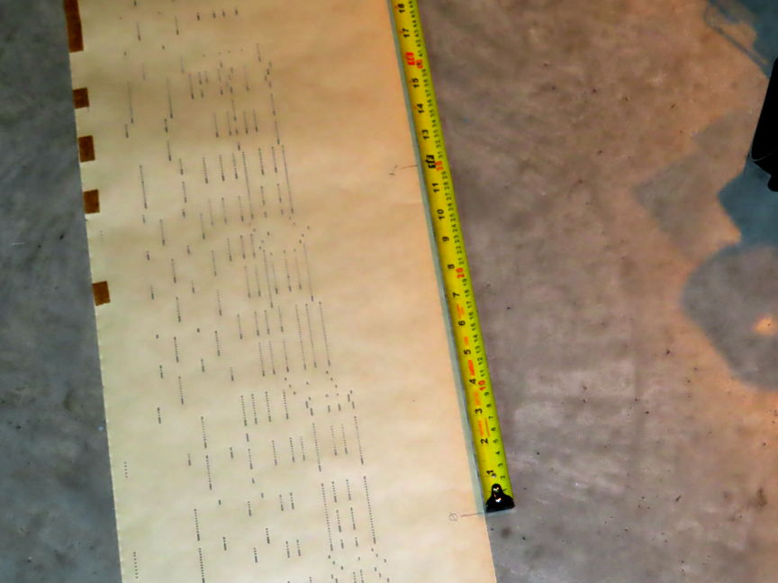
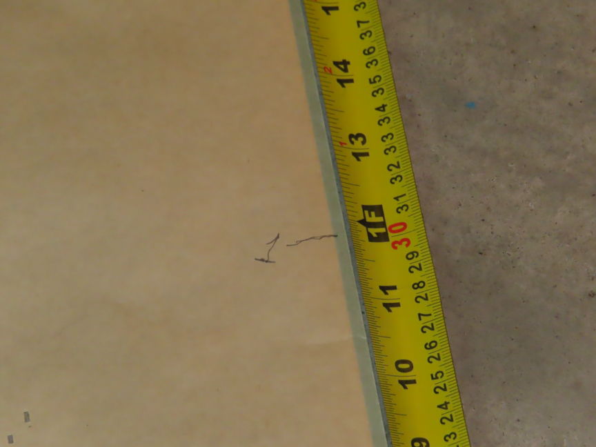
figure 25 – writing marks on every 1 foot length.. up to 14 feet.
*** Write software for paper
scrolls step motor speed & BPM meter ***
*** PLAY position paper scroll ***
Now I could do some speed tests with the scroll stepper motor
by playing with the PIC16 TIMER1 interrupt time
driving it and vary the interrupt time with the help of a ‘Speed’
potentiometer.
The potentiometer’s ADC values are put in a lookup table that
hold all the 13 important ‘delays’ to put in the interrupt function
to drive the stepper motor at the good pace for each of the 13 different BPM
speeds.
Instead of varying the speed continuously on the pot’s wiper I ‘fragmented’ the
ADC readings
by 13 programmed values that correspond to 10BPM at min speed
and up to 130BPM at max in 13 equal rotation steps.
So, I played the marked paper starting
at an unknown slow speed and stop timed
from the ‘0’ mark up to the ‘1’ mark. And wrote the actual time it produced.
For the 10BPM I’d need markings 0 to 1 to take 60sec. precisely.
So, I adjusted the TIMER1 interrupt time
to generate the good timed
stepper motor pulse accordingly. I made this same procedure for all the 13 BPM
speeds.
… Very long and painful work to do
that...
*** REWIND position paper scroll ***
Because the
PLAY and REWIND positions do not use the same roller’s gear arrangement
(Bigger gear on REWIND position... runs
around 5 times faster! )
I could not use the same TIMER1 timings
to drive the scrolling motor
so I calculated a second lookup table to accommodate the slower REWIND timings,
Doing so both PLAY/REWIND positions show around the same paper speeds
when selected by the speed potentiometer.
*** Installation of new front
BPM indicator using green LEDs ***
Now that I have a lookup table
containing the 13 scrolling speeds
and selected by 13 ‘fragmented’ potentiometer ADC values,
I could use these 13 ADC pot values to actually select and lite one of an array of 13 front green LEDs
to show the actual selected BPM speed. 13 LEDS would need too many I/O pins
from the PIC16 so I decided to use 2 x external SPI to 8 bits Parallel
peripherals.
74HC595 ICs will be very nice for this
job. 2 of them for 13 LEDs
will only use 3 x I/O pins. Perfect !
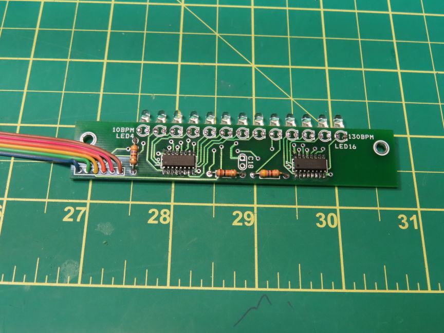
figure 26 – The 2 x SPI to 8bits Parallel
ICs 74HC595 mounted on a small PCB
And what about lighthing
this black BPM metal plate ??
Even with a max of 2 BPM green leds lite at a time
this plate sits in a dark area of the lower spool
and is difficult to see even at day light.
And because the upper section of this metal plate needs
to be far enough of the lower spool,
(using ‘fat’ big paper rolls will have tendencies to scrub the metal plate !)
So I had to figure a ‘slim’ way of lighthing.
I thought I could use an array of small LEDs connected in series
and attach them at the front top of the plate, but again
the pcb to hold all these LEDs will still be too big
placed at the top
and could damage the lower paper roll. Then I found this:
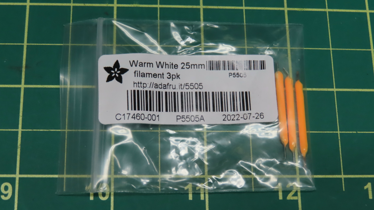
figure 27 – 3 x ‘Filament’ LED arrays
working at 3VDC each.
The Adafruit company sells tinny 360deg glowing LED
array bars (#5505)
that work at 3VDC (30-50mA). These arrays produce a ‘tungsten like’
color that is emitted all around the bar. These bars have a diameter of around
3mm
and could be connected in series with a limiting current resistor to my 12VDC
supply.
So, I designed a thin metal plate that
could hold
and hide 3 of these bars in place and stick the plate at the back top
of the BPM plate. See the following pictures:
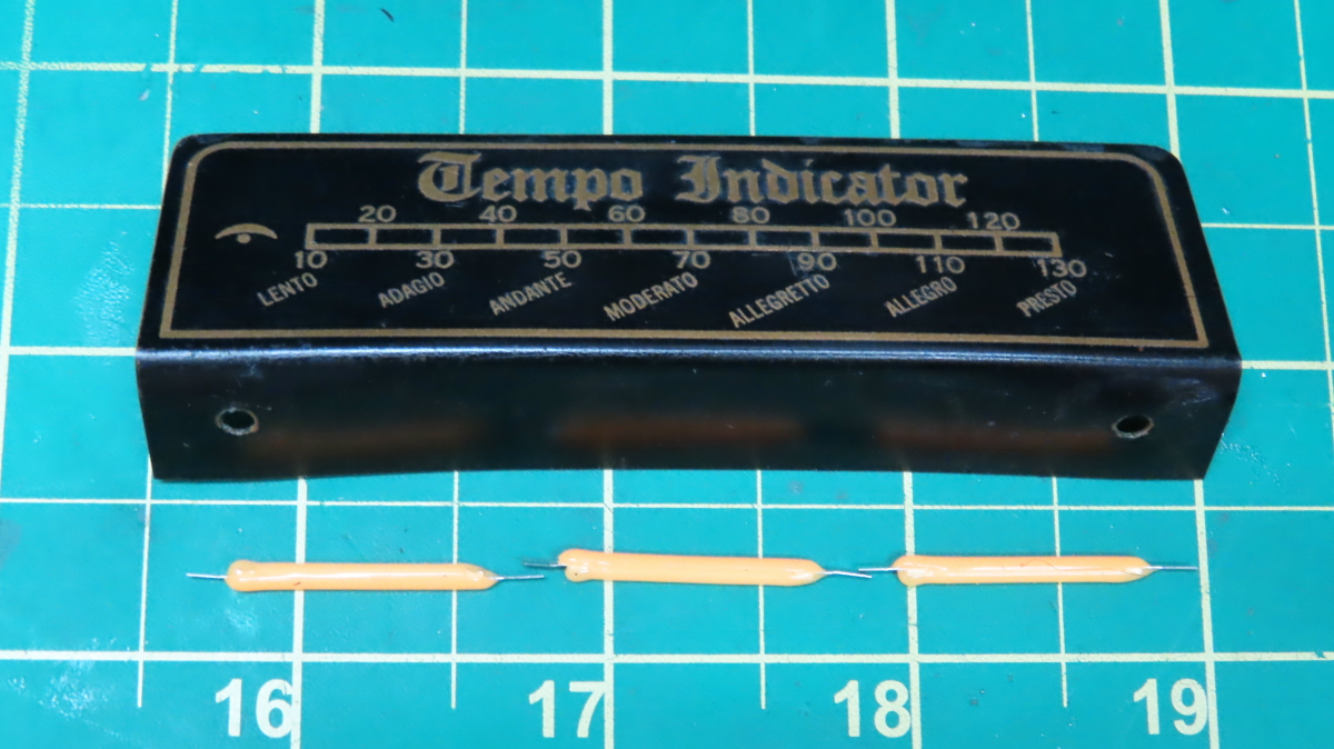
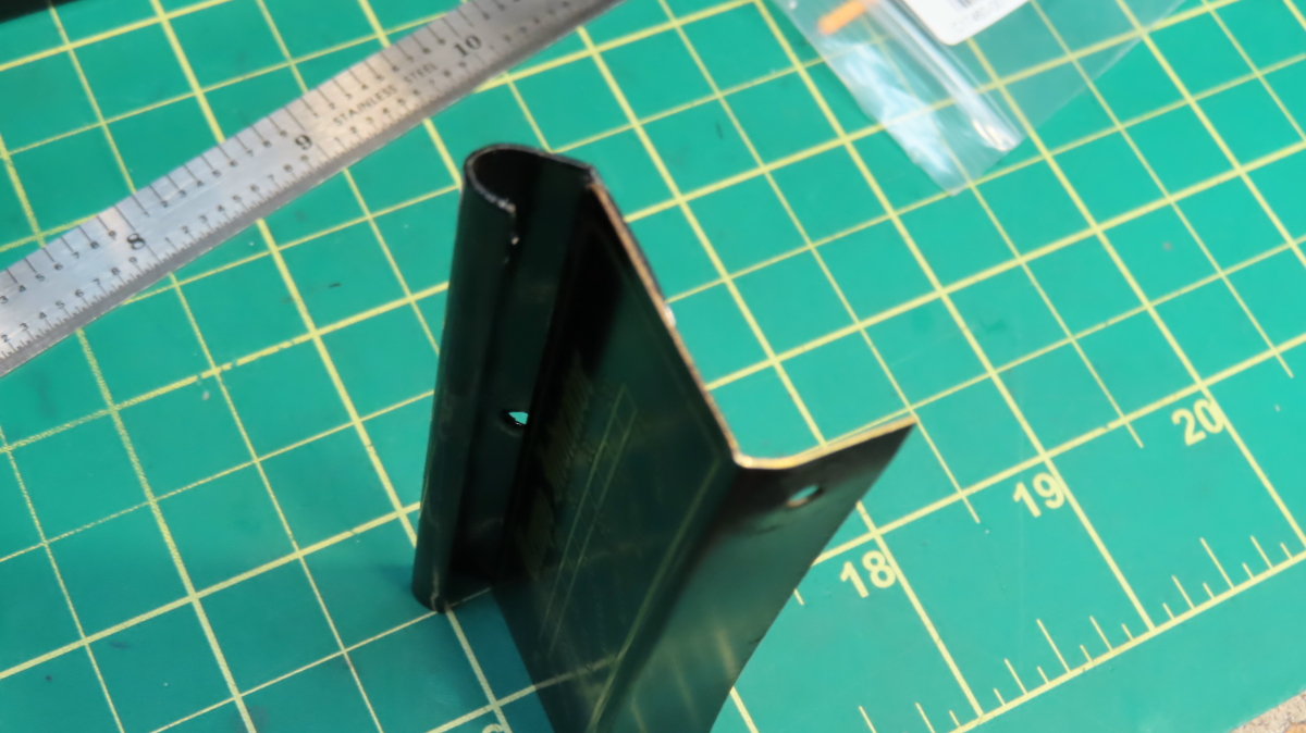
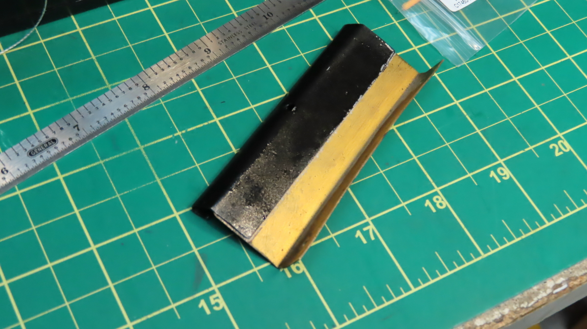
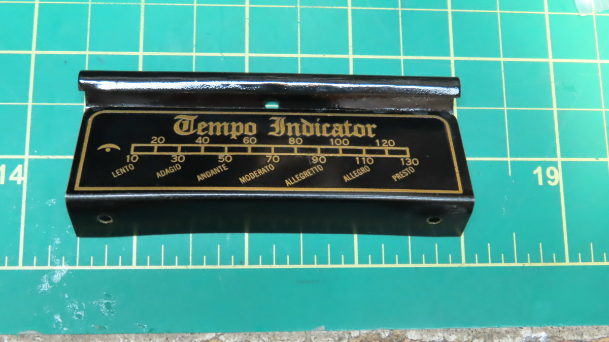
figure 28 – 3 x installed ‘Filament’ LED
arrays hidden inside the top curved glued bracket.
A 12VDC connector is ready to be
connected to the back of the BPM plate
to a ‘not shown here’ 2 pins male connector that will
supply around 30mA to the three LED bars through a 100R 1/2w resistor.
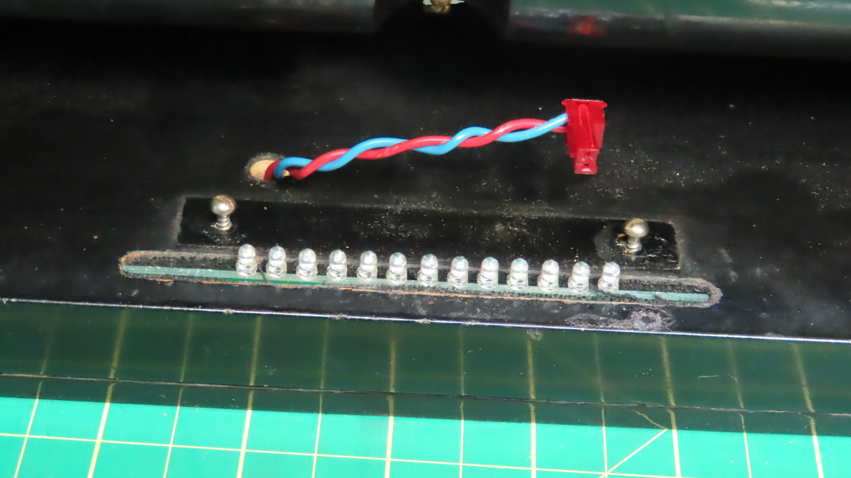
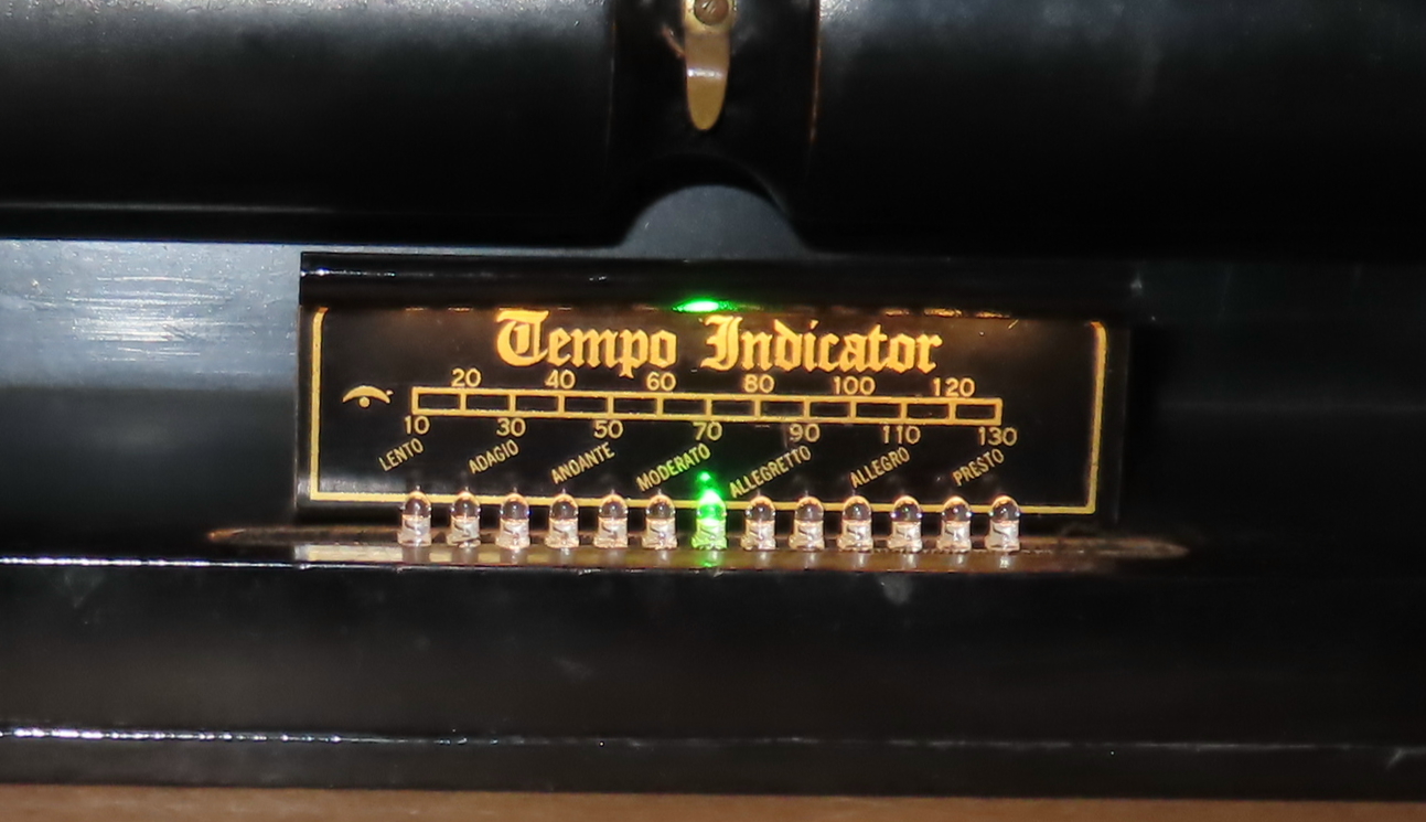
figure 29 – The 13 x green BPM LEDs
installed, 70BPM selected, with Filament LED bars at the top
Note: The BPM green LEDs light up ONLY when the PLAY/REWIND actuator is
in PLAY position.
Now that all the paper scrolling
mechanisms have been installed and working
I can start the tedious process of optically reading the brass tracker bar’s 90
holes.
*** Installation of 91 optical
sensors with their light pipes ***
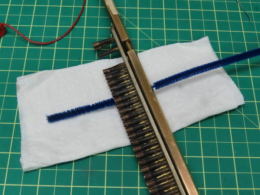
figure 30 –
Cleaning all the 91 tracker holes with Pipe cleaner straw
Since all the 91 holes had accumulated
dust and particles
over their life time it’s time to get them cleaned up.
Figure 30 shows an easy way to get things done.
After a thorough complete clean up of
all the holes
It’s time to start building the 91 optical sensors
or IR photo-transistors and get them inserted in their
respective small brass tubes.
I used a twisted pair length of AWG#22
hookup wire
to wire all the 91 sensors sections:
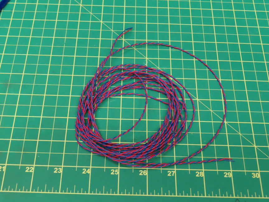
figure 31 –
Twisted pair of AWG#22
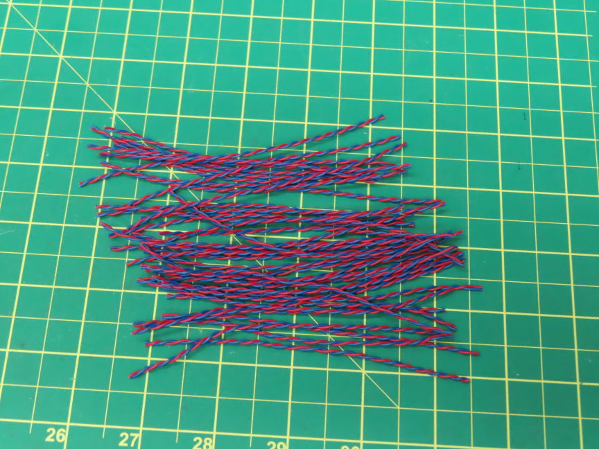
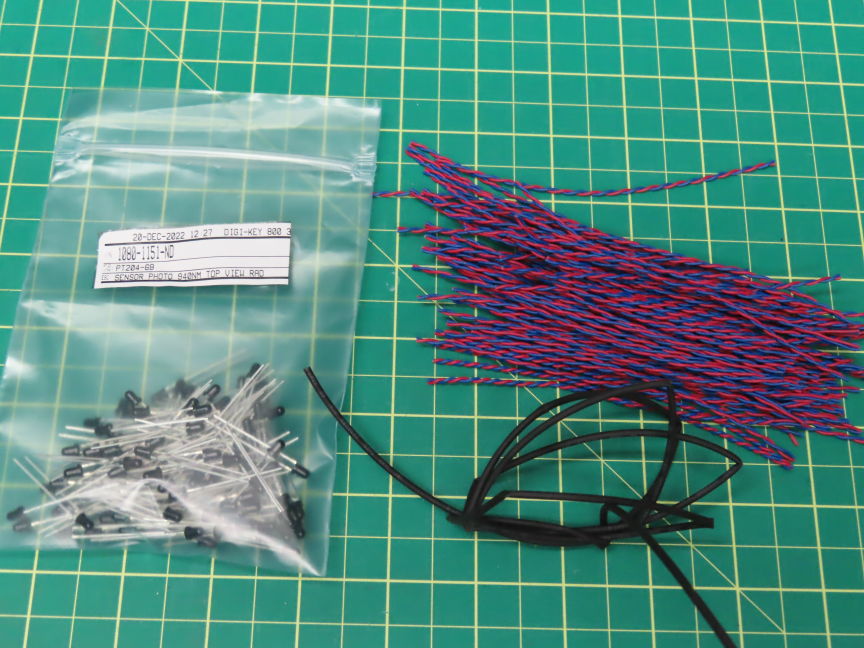
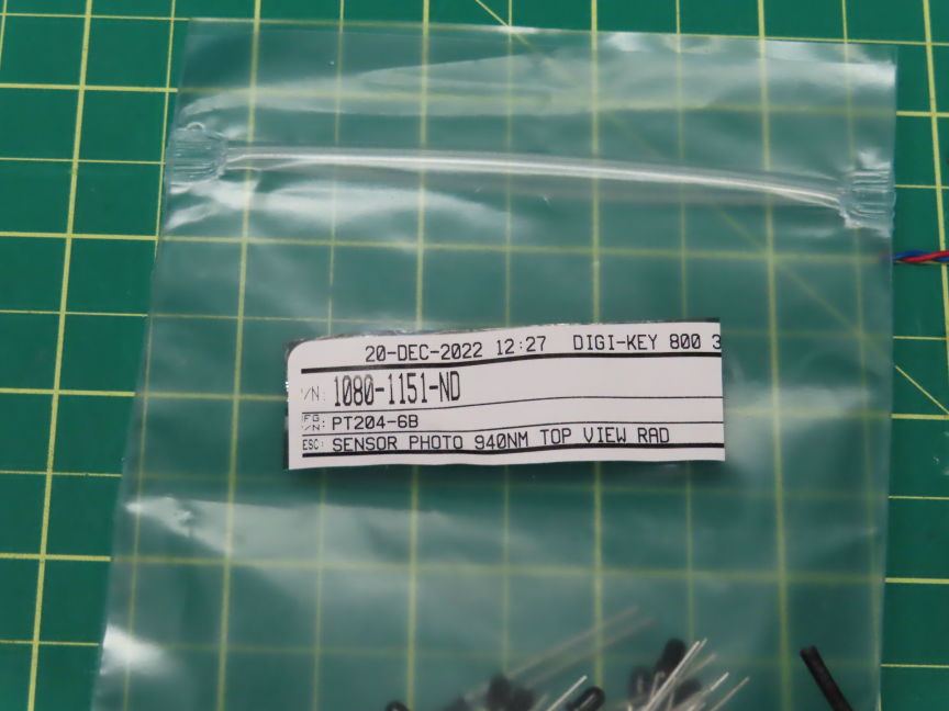
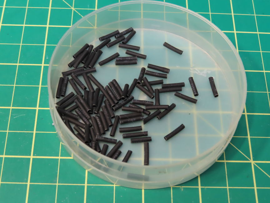
figure 32 –
Preparing stuff for 91 sensors
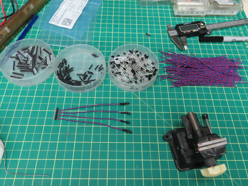
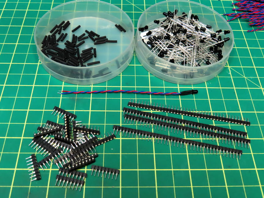
figure 33 –
Still preparing stuff for 91 sensors
On figure 33 you can see inside the left bin 22 x 8pins strips
of 0.1” pitch inline socket connectors. These are from 40 pins strips
cut in 8 pins lengths. 8 pins strips are for 4 sensor wires including their
respective grounds.
See a completed strip here:
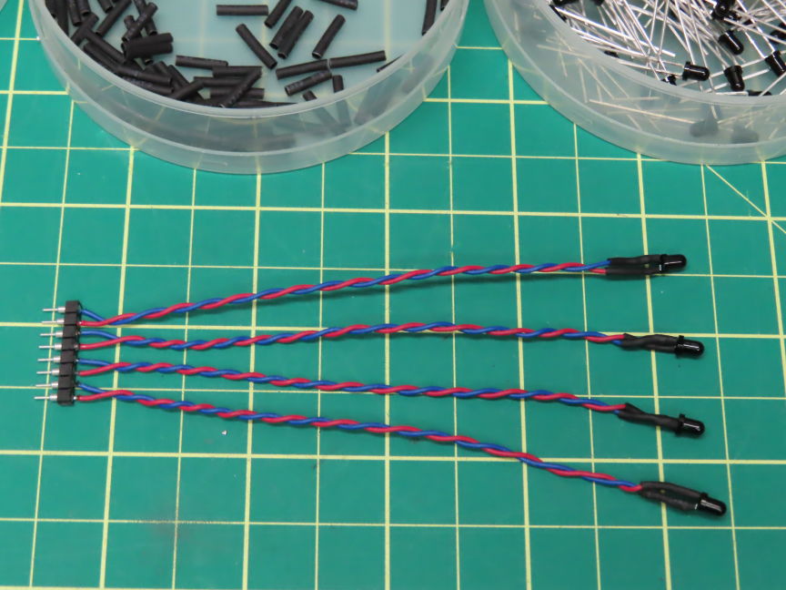
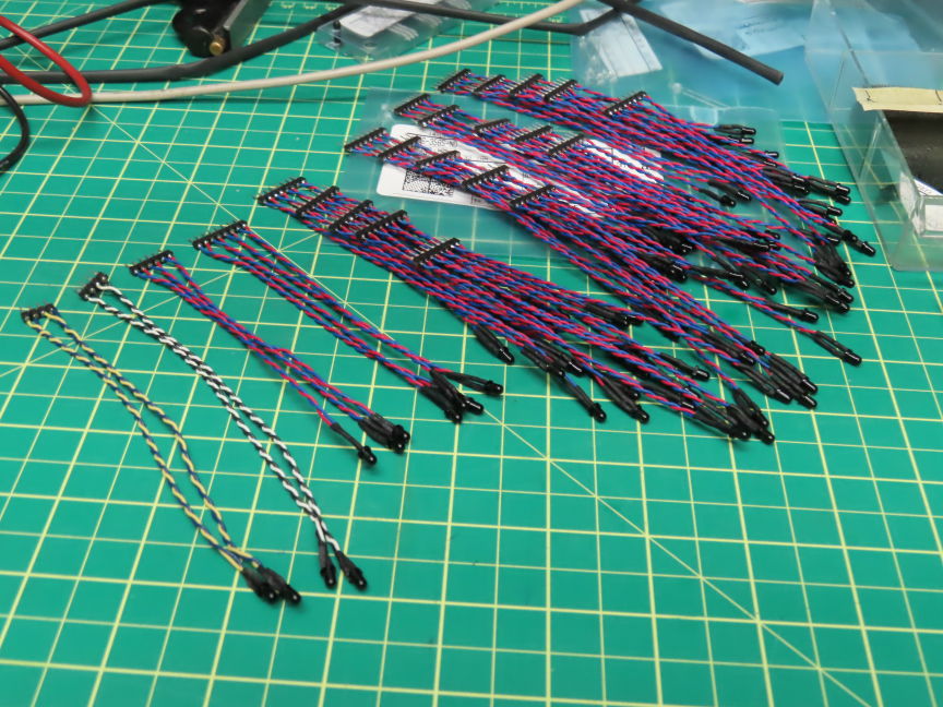
figure 34 –
Detail showing one all the assembled strips for 87 + 4 x IR sensors
Since
8 sensors would need 2 of these 8 pins strips, for 91 (87 + 4 paper edge
detectors) sensors to be installed
I will need 22 x 8pins strips + 2 x 4 pins strips to be assembled.
The last 8pins strip will only provide for 3 sensors (85,86,87) so will be cut
for 6 pins.
The paper’s edge detectors strips only need 2 sensors each so 4 pins each.
*** Test all the 91 optical
sensor’s gains and accuracy (DC voltmeter) ***
Ok. Now that all the needed sensors
strips are assembled, I faced a big problem
about the individual IR beam strength to reach each sensor.
Since the front of the brass tracker bar will be ‘front lite’ by a large array
of 48 x Infrared LEDs,
to perform the optical readings of each paper holes, the emitted ‘band’ of IR
beams from
the front array of LEDs must get through each of the tracker bar’s holes and
reach each
individual photo-transistors (sensors) strongly enough for good ON/OFF notes
separations.
Hope you are still following me here. The problem I faced is that the distance
the front IR LEDs are from each IR sensors exceeds 1.25” in length!
see the picture below.
figure 35 –
Distance the IR beams would need to travel to reach sensors
Since all the
photo-transistors are powered from 5vdc,
with no paper over the tracker bar, and full IR beam strength on the tracker
bar holes
I could not get good photo-transistors saturation but only unexpectable ‘close
to 5vdc’ floating DC voltages
far from ‘saturated’ close to zero-volt readings as it should be...
The solution... Light
pipes installed in front of each IR
sensors to help carry
the tracker bar’s front surface IR beams up to the sensors tips.
Here is a picture of this configuration:
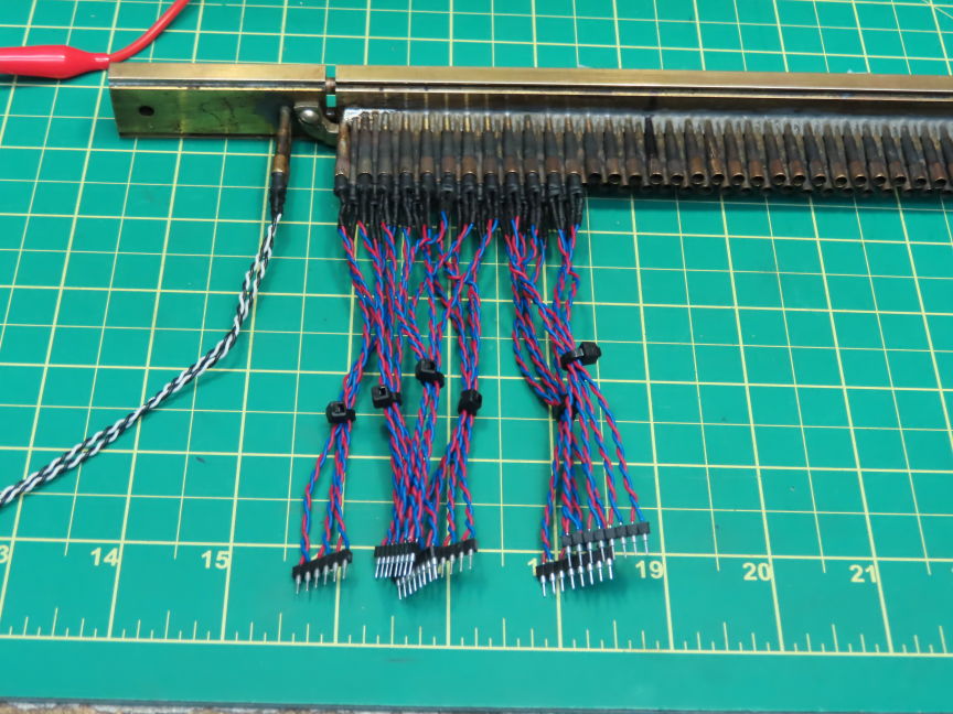
figure 36 – Light Pipes over
IR sensors tip installation details
With these light
pipes installed across each tracker bar holes and their respective sensors I
could see
a very big difference in the sensor’s saturation readings. Very noticeable
ones!
But I noticed that some sensor’s saturated readings were still too high (too
close to 5vdc)
and I wondered why... When checking these sensors, I pulled them out
of their back brass tubes to check their
condition. Oooohhh.
I found these ones had their light pipes cracked or broken in their middle
enough to be seen. Here is a picture one of these broken light pipes:
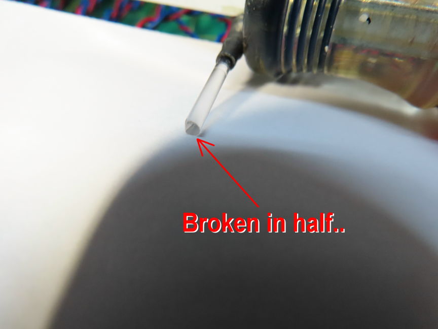
figure 37 – Broken light
Pipe details
Even a very
small crack in these light pipes caused a very bad IR beam travel attenuation
and would keep the attached photo-transistor from saturate enough
for a good LO digital state. So... I found that I had to replace around 25 of
these
installed light pipes with other good ones. Iark…
These light pipes are made of ‘glass like’ material so they are very brittle.
The 2 following pictures show how the front 48 x IR emitters LEDs array
have been installed.
These are installed on a ‘hinge type’ support which is very handy to correctly
position the array for the very best & strong IR beams over the 91 holes,
and sometimes to lift the whole array for inspection.
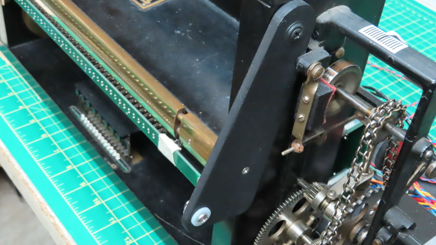
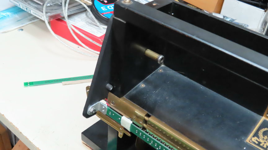
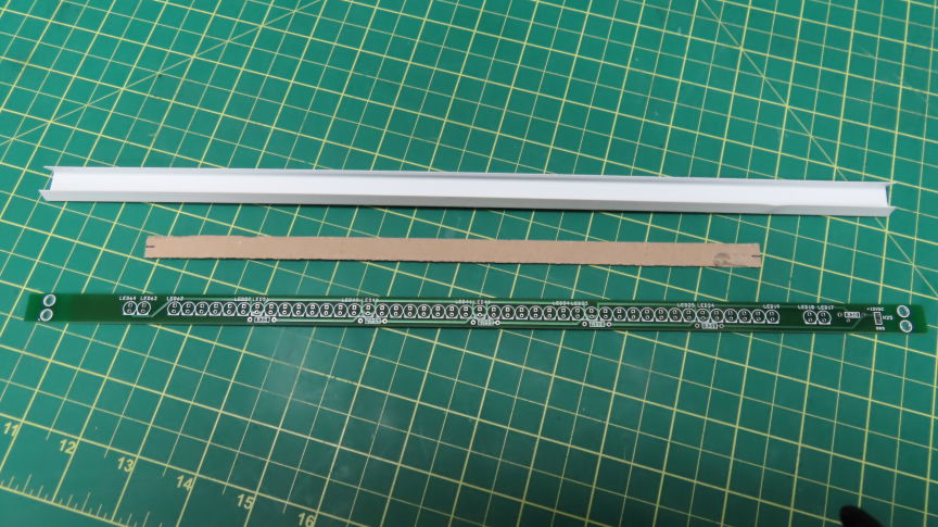
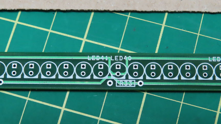
figure 38 – Front PCB with 48 x IR emitter
LEDs array mounted on liftable hinge
You can see on the 2 top pictures that parts of the PCB have masking
tapes.
These are sections of the PCB that needed 4 LEDs to be shrunk
and dremmeled to precisely face the far
left/right paper edge holes detectors.
These holes were almost overlapping and very close to each other
which involved 2 pairs of ‘glued’ LEDs to fit the needed IR beams
The following picture shows the 4 paper edges detector holes:
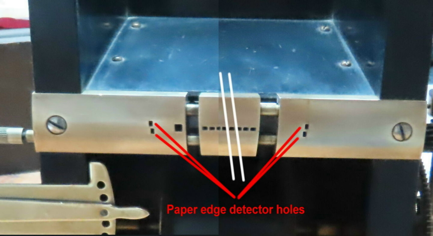
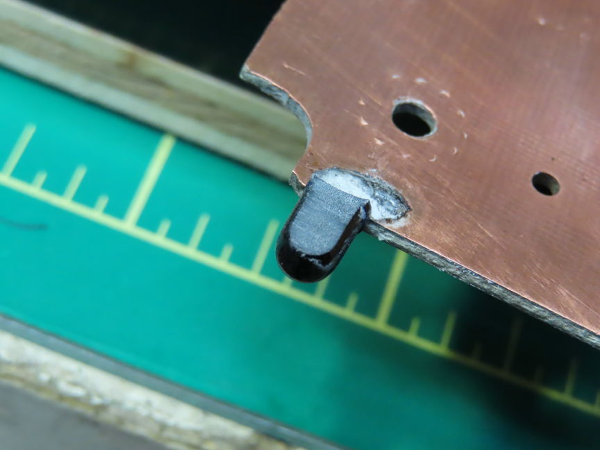
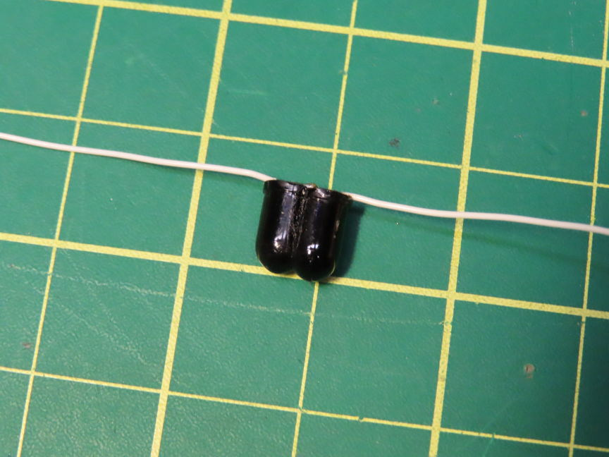
figure 39 – 4 x paper edges detector holes
& dremmeled pairs of LEDs details
These modifications were of ‘last minute’ and needed the IR LED pairs
to be glued with epoxy over the PCB LED array left and right sides
facing exactly the edge detector holes.
The
job worth doing it since all the final readings were strong ones.
On the following Excel spread sheet you will see how close to zero volt all the
sensors
are with full IR beams crossing all individual light pipes:
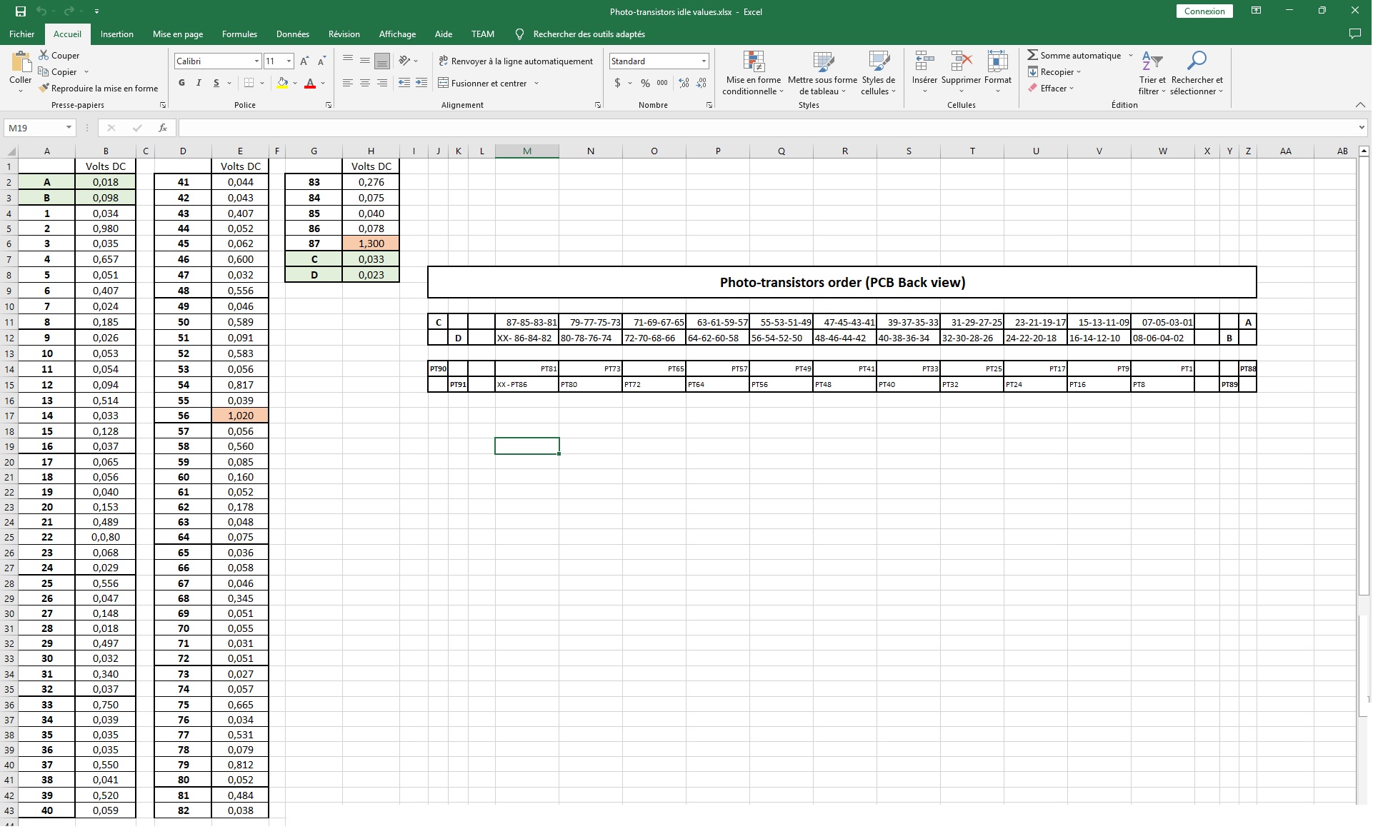
figure 40 – Light Pipes installed 91
sensor’s saturation DC values
The Excel spreadsheet shows only 2 sensors that read a little over 1 DC
volt
which is easily saw as 0 or LOW digital level then acceptable.
A diagram of all the 91 photo-transistor positions is also shown at the right
side
viewed from the back of the completed machine.
*** Test the 91 optical
sensor’s digital reading accuracy (without jitters) ***
To perform all the following sensors tests I connected a MIDI external
synth
to the MIDI out connector on the main PCB, set to MIDI channel 2 (the external
synth needed that).
The MIDI channel selector needed to be placed on position 1 (which gave MIDI
channel 2).
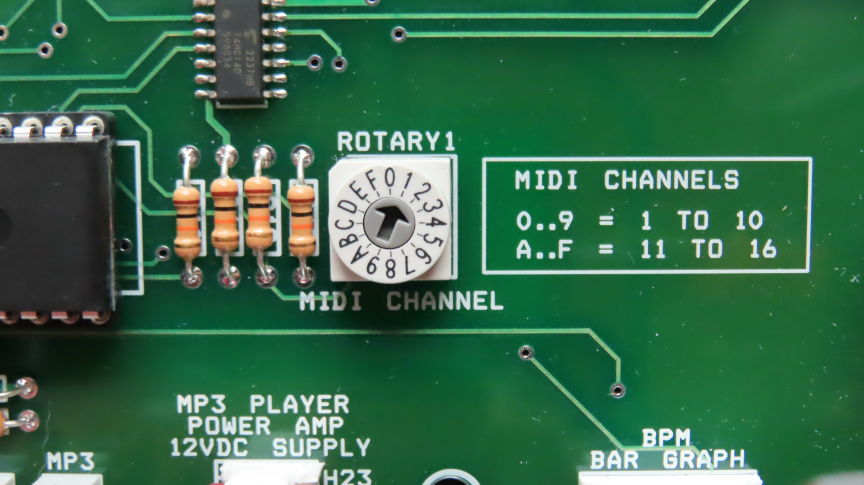
figure 41 –
MIDI out channel selector
Now that we know that all the 91 photo-transistors gains are acceptable
and ready to be read with the help of digital micro-controller I/O pins,
we need 87 + 4 x I/O pins to do that job.
Well... no existing micro-controller would ever have this number of I/O
pins available
on one package, so the solution is to use SPI external devices such as the
74HC165
8 bits parallel to serial SPI buffers. They can be daisy chained to be able in
our case
to read all the 87 piano notes sensors. Doing so, only 3 micro’s pins are used.
(The 4 paper edge sensors will be read from standard I/O’s).
So I installed a test paper roll on the machine and did some scrolling and
readings of the first paper’s holes.
After some digital measurements of the actual note’s waveforms acquired from
the PIC16 micro
Instead of reading expectable sequential notes from the scrolling paper I was
getting lot of fast ON/OFF readings
much over the number of notes that were on the paper... Hmmm...
I connected an oscilloscope to one of the PIC16 test-programmed
pins to show in real time
how one of the read holes was ‘seen’ by the micro, and here is what I found:
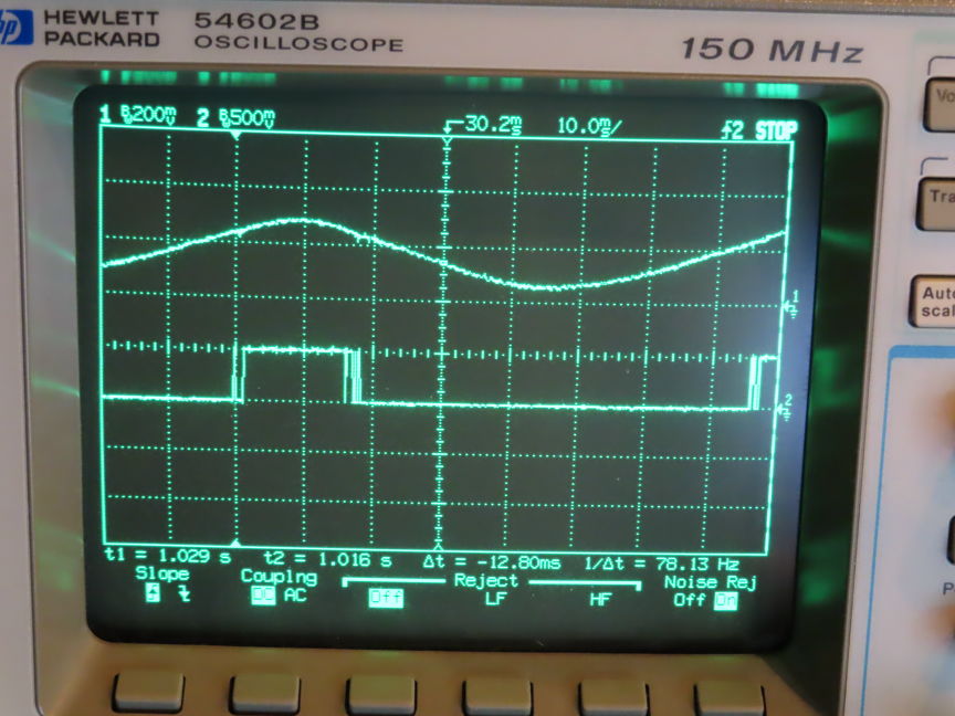
figure 42 –
Stretched view of one fast going paper hole viewed by the PIC16
Figure 42 first shows the upper trace with a very stretched
up/down 0-5v going pulse that comes from the
tested photo-transistor’s collector. It goes from around 0.5v to 3v max.
The lower trace shows what the 74HC165 related pin sends to the PIC16.
We can easily see the jitters created around where the 74HC165 threshold
level is reached
in the up and down going regions. And these are all these fast-going pulses
that are read
by the PIC16 and added to the normal ON/OFF values that should only be read.
The reason for that behaviour is that the 74HC165 have standard inputs.
These inputs ‘hesitate’ on slow readings around their input threshold values
between LOW or HI to be read.
The solution, to use 74HCS165 chips which have embedded Schmitt trigger inputs.
Using these chips completely got rid of all the jitters. Clean notes readings
now!
*** Dotted type lines of long
duration notes... how to read them ***
Now that I can read paper roll holes correctly with the PIC16 I’m facing
another challenge...
Because of the fragile tendencies of paper roll to break when manipulated some
manufacturers
used ‘dotted’ holes lines for long duration notes instead of steady cut all
over the note duration.
This process is shown on the next picture:
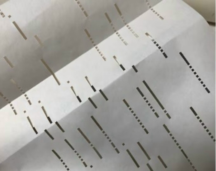
figure 43 – Long duration note
fragmentation of the cutting time to play
Dotted holes lines keep paper in better condition & stronger over
time to be manipulated.
The problem with these successive holes when encountered is that on reading the
playing machine would ‘follow’
these dots as separate notes to play and would create a ‘staccato’ playing
which is not
what the original piano player recorded on paper!
The following picture shows what the PIC16 would ‘read’ when dotted lines are
encountered:
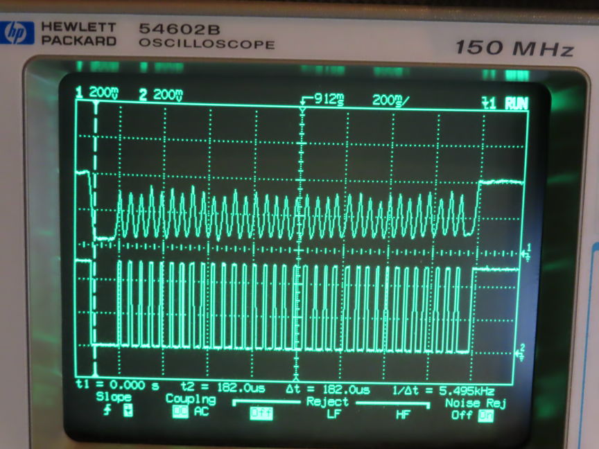
figure 44 – Dotted line reading details
On Figure 44, the upper trace of the oscilloscope screen snapshot shows
one of the photo-transistor’s
collector to its associated 74HCS165 SPI buffer input pin. The optical result
swings from
4vdc (paper blocked IR beam) to around 0.3vdc (full IR beam detected).
You will notice all the small peaks detected over the long note’s duration
until the signal swings back up to 4vdc (ended). These peaks are better shown
on the lower trace
as digital pulses detected from 0 to 5vdc. These pulses would be interpreted as
successive
separated ‘staccato’ notes if not ‘filtered’ with software.
After over 5 days of programming tests I finally figured a way to ‘fill’ these
successive holes
and get a steady note with no fragmentation occurring.
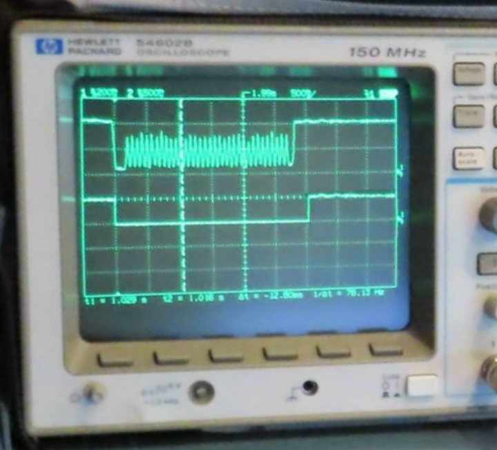
figure 45 –
Dotted line reading with filtered action. One steady note remaining.
The upper trace of the oscilloscope screen snapshot shows one of the
photo-transistor’s
collector to its associated 74HCS165 SPI buffer input pin. Again, the optical
result swings from
4vdc (paper blocked IR beam) to around 0.3vdc (full IR beam detected).
Now the lower trace shows how the software filtered all the incoming peaks
and flattened them out to get a steady and single low going pulse.
You will notice the ending hi going pulse on the lower trace is delayed
compared to the upper trace hi going ‘note ending’ one. This is due to the
software filtering counter
that ‘counts’ for a real end of note occurring before really ending the
incoming note.
*** Figure out and finalize
paper auto-centering mechanism ***
Now that all the 87 notes sensors are read correctly and that the scroll
motor works by the player piano speeds standards
we can focus on how to make the paper scrolling travel with auto-centering.
On playback, when a piano roll is pulled down by the low pulling roller it has
an easy tendency to be
dragged to the left or to the right along its song period. This behaviour
causes the scrolling paper holes
to get unaligned against the tracker bar’s array of holes, then producing
unreliable readings and lots of missed notes.
So, the playing mechanism needs some kind of auto-compensation for the
paper centering
to keep the playing aligned and steady for any playing speed.
figure 46 –
Paper centering original Brass bar holes.. LEFT and
RIGHT
Figure 46 shows 4 x holes dedicated for the paper centering process.
2 for the left readings and 2 other for the right readings.
The original auto-centering mechanism was made using 4 x pneumatic
rubber pipes
connected to a 2 bellows tank that activated left/right movements of the
upper roller
so auto-centering the paper along the playing of a song.
Now I needed to achieve the same auto-centering but optically...
I started using all the 4 edge detector sensors involved and did many tests
that would make me conclude the following:
Over time many of the paper rolls get damaged by dryness and heat. Their
overall width can be affected
and would be hard to rely upon (by the mean of the tracker bar left/right edge
sensors).
And one major thing was the way the 4 edge sensors would respond when the paper
edges
are detected or not when passing over them. I could not achieve the same
reliable work the original 2 bellows pneumatic system would.
I finally determined that using 4 optical edge sensors was not a good way to
auto-center the rolling paper...
So, what else could I do?
I took a piece of paper and started to do binary calculation of how the paper
edges behaves
and some way to reliably ‘track’ the paper drifting’s and stop them along the
played song.
I finally found a very easy way to do it.
Only use one of the 4 edge detector sensors (the lower left one) and use it as
follow:
The far-left lower edge sensor is used here and will only read HI or LOW from
what’s passed over it. OK.
Just
assume the paper is too far left:
The paper will completely cover the detector hole making a digital HI reading.
Now let’s assume that the paper is too far right:
The paper will not cover the detector hole at all making a digital LOW reading.
This means that the ‘ideal’ aligned
positioning of the paper is where the ‘Transition Zone’ is,
which is an impossible zone to stay on, BUT we can continuously try to reach it
slowly going left – right – left – right -- and so on..
Here is a small diagram of this process...
Transition zone
______________________
_|
HI,
No IR beam so
|
LOW, IR beam passing so
Paper over sensor
| edge too far right that let beam pass
Push paper to the right | Push the paper to the left
|_______________________
The following picture shows the 2 actual paper positions that would imply
a ‘move’ of the centering motor. The 2 positions have been exaggerated
to best show both conditions, but in reality the paper left-right move
on the tracker bar never exceed around 0.5mm which is very good for a tracking..
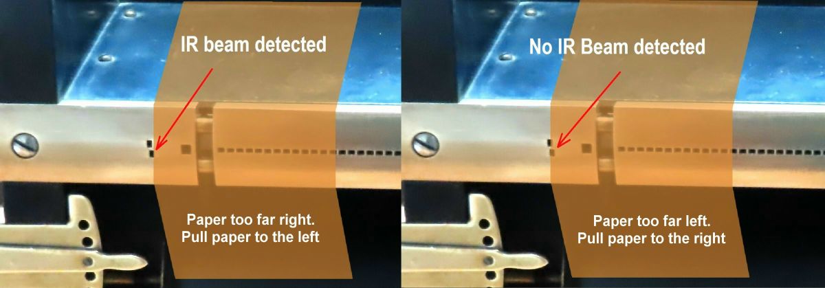
figure 47 –
Auto-centering detection of paper needing to be re-positioned
Now that the PIC16 has a way to figure where the paper’s edges are
placed on the tracker bar
it can decide how to act to correct the paper left/right position.
The paper position correction is made by the help of a second stepper motor
who’s shaft turns just a little left or right moving a steel rod attached to
the upper supplying roller shaft itself.
The stepper motor speed is programmed to be very low with a calculated inertia
to be not too fast, not too slow.. Just the good correction speed (compared
with a real pneumatic compensation speed).
The following closeup is a view of the back centering stepper motor with its
steel rod attached to
the upper supply roller to adjust its left/right position.
The right image shows the front needle showing the ‘real time’ paper
positioning.
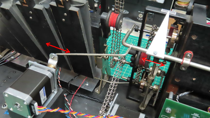
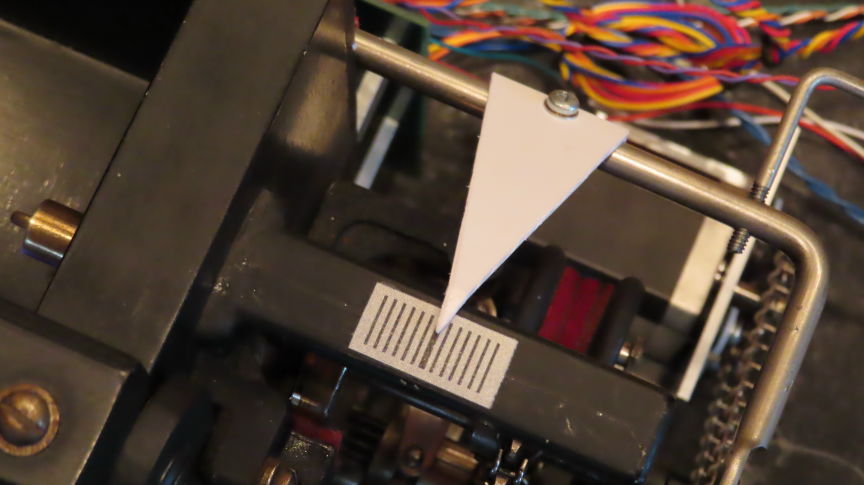
figure 48 –
Auto-centering stepper motor positioning system
Without this auto-centering system I had around 15 piano rolls that
would absolutely
not work on the machine because of their pour paper quality and waving
behaviour while playing.
This auto-centering made them work again flawlessly!
On all the rolls playing I checked the holes alignments for any misbehaviours.
No problem found. I could see the centering stepper motor do its job by
continuously pulling/pushing
the upper supply roller shaft. But... Some paper rolls however need an ‘offset’ adjustment
before starting to play. Their ‘almost the same’ width (compared to other
rolls) needs this tweaking.
This is done with the help of a small screw type slider placed
just above the left transpose key shown here:
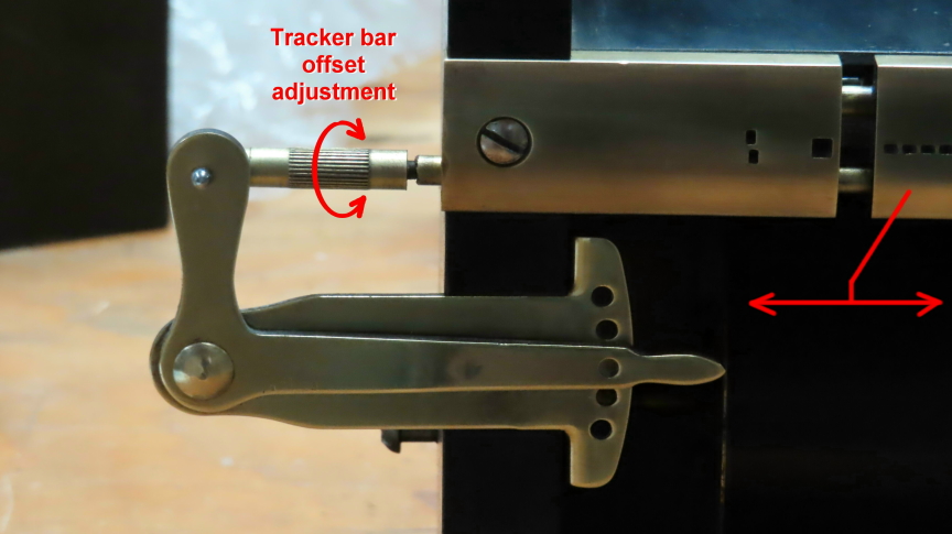
figure 49 – Tracker bar offset adjustment
screw
Turning this screw slider makes the complete tracker bar center
move left-right
depending on the direction the screw is turned. The distance moved is just
enough to readjust
the alignment of both the paper holes and those of the tracker bar.
After this offset adjustment nothing more to be done to precisely play that
paper roll.
*** Testing paper
auto-centering mechanism while listening notes (software) ***
Now that I had the paper auto-centering
working I just needed to do a real test with a QRS test paper roll.
This test roll tests all the piano keys successively one after the other. It
also performs big successive chords.
The test passed with success! No notes missed at any speeds! Now I want
an ‘installed’ MIDI sampler player with piano sounds.
*** Installation of MIDI
output cable between main PCB and MIDI piano sounds module ***
Ok. All the piano roll player is now
working and ready to drive, thru MIDI control,
a small MIDI sound module with piano waveforms installed. My project will be
‘standalone’ and able to play
songs without any other audio device connected... To do that I need a small
MIDI sound module that
can read incoming notes via MIDI protocol. My project offers 2 separate MIDI
outputs.
One connected to the Yamaha P50m for ‘stand alone’ uses via
a DIN male connector connected to its INPUT, and the other MIDI
output is connected to another MIDI female connector for external connections
to any MIDI devices for added sound variety.
Introducing Yamaha P50m piano sound module
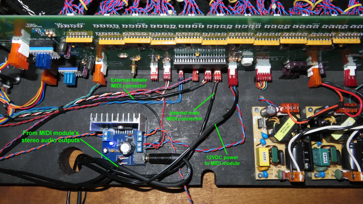
figure 50 –
Yamaha P50m module connected to a 2 x 20W power amplifier
The stereo power amplifier outputs were
connected to 2 small MINIMUS 20w sound boxes
that will be attached inside the complete machine’s case.
*** The 2 x 20 watts power
amplifier ***
One note about the TDA7297 based bridge
power amplifier board:
I found that the overall stereo power was easily distorted when pushed a little
on both channels.
So, I checked both +/- leads of each left/right channel output
connectors.
I first connected the – lead of left channel output to my oscilloscope.
GND lead of scope to GND of power amp,
and played a roll. (One side of the bridge output tested).
When powered by a single polarity +VCC, the TDA7297 IC has a bridge output
configuration, so
both + and – output pins of each channel should go from idle VCC/2 volts and up
to around VCC or GND
but inverted together. Well, that’s not what was happening. Only the + output
pin was swinging with music.
The - output pin was stuck in the VCC/2 position... no signal! Same thing on
the right channel.
So the amp was working at a much lower possible output power that it should.
That meant one thing... I had a fake TDA7297 IC on my amp board! This board was
purchased from Aliexpress for $7.00US
So I ordered a genuine one from Digikey, a reliable seller.
Here is a final view of the piano roll player’s front controls:
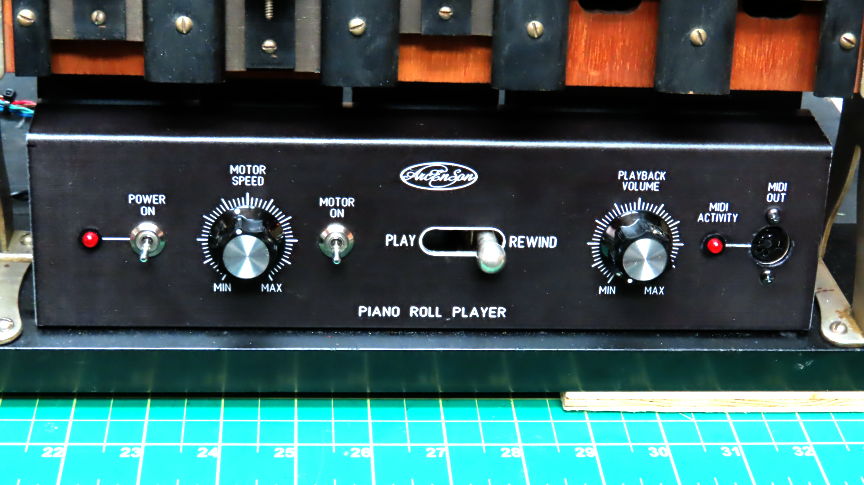
figure 51 – Front panel controls
While in the design process I found very
cute the old 5 x vacuum bellows activated motor
that originally powered the rollers by the user’s pedal actions and decided
to keep it geared to the scrolling motor mechanism.
This unit still ‘pumps’ air while the machine plays or rewind:
figure 52 – Original 5 x vacuum bellows
activated motor
*** Final cabinet that holds
all this project.. ***
This project needed a cabinet to hold all the necessary electronic
hardware
including my collection of around 100 paper rolls I already had.
So I designed a decent cabinet made of ½” Russian plywood
with enough compartments to store the paper rolls.
Here is the actual cabinet drawings and final appearance:
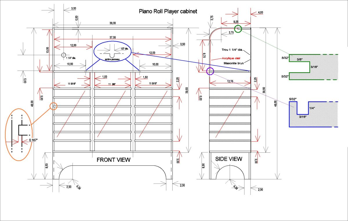
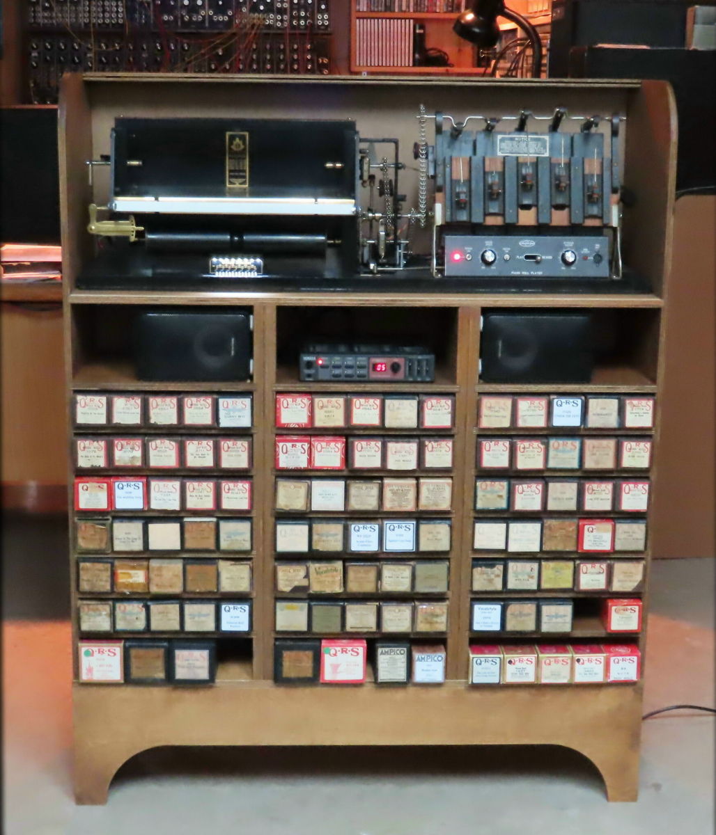
figure 53 – Project’s cabinet drawings and
final appearance.
So that’s it !
Thanks for watching and feel free to ask
any questions
about this project using the email below..
If you’d like to have a look at some of my other projects
Just go to www.arcenson.com/projects

2023