My FM stereo
encoder project
based on the Pira CZ
stereo encoder
This project started some years ago..
One of my passions is fixing old vintage radios.
To make things easier I had to buy some good test equipment’s.
So I bought a nice Marconi
2022E RF generator
like this one:
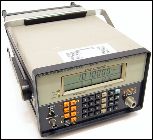
Marconi 2022E RF generator
This RF generator could do nicely AM and FM
modulation
on all the broadcast bands.
For the AM side there were no problems so far.
But when you talk FM radio repair you need some
kind
of FM stereo generation to get the radio’s
demodulation section works correctly.
Fortunately my new acquired Marconi had an external
modulation input.
So I needed some kind of FM stereo multiplexer unit
that I could connect to my generator…
The search started around the net..
My quest for the very best and not too expensive
kit of this kind
brought me to some
available solutions.
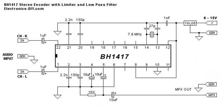
Like this one based on the
BH1417 Stereo Encoder chip
or this one based on the
NJM2035 chip
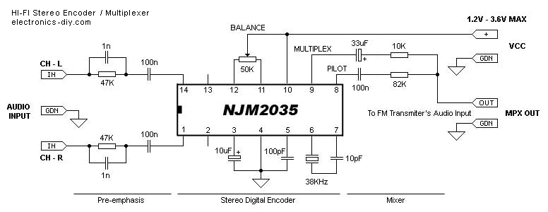
Both of these solutions were ok but when I started
to go further
in their
circuit specifications I noticed that the audio frequency spectrum
for both of these chips was not quite good and
worst of it
there was lots of harmonics generated by the inside
multiplexer !!!
And their filter sections were not very sharp, neither efficient..
So I browsed deeper on the net until I heard about
a very nice
and accurate stereo MPX FM encoder available in kit.
Introducing the Pira CZ Stereo Encoder for FM
Broadcasting
Here is a snapshot of the web site description of
the product:
This stereo encoder is a halfway between analogue and
digital processing.
It combines the best from both domains to provide high-quality and easy to
build device.
The sampling frequency used in this stereo encoder is 97 times (!!!) higher
than the pilot tone frequency.
This makes very easy to reject all spectral residues around the sampling
frequency without affecting the main signal characteristics.
Using of a microcontroller allows to build this stereo
encoder with reduced part count and get excellent results in real
operation.
But since this web site did not sell any of these
boards
I had to figure out where I could buy one..
Here comes eBay to the rescue !
You can buy a bare PCB of this encoder for less
than $18.00US + s/h.
Here is how it looks:
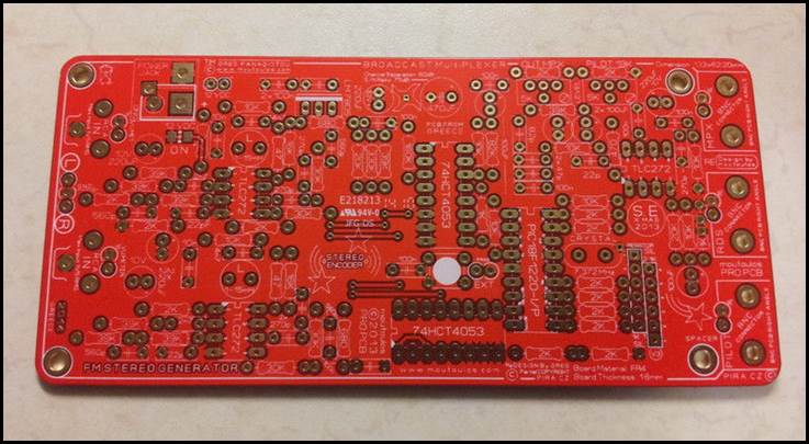
FM
Stereo Generator Encoder MultiPLEXER BroadCAST PCB (PIRA) by moutoulos
™
The only thing that is sad about this PCB is that
the seller
did not provided
any parts kit or even a single parts list..
So I now had to check the original PIRA Encoder web
site
for any parts list and description of the actual
circuit behaviour.
Fortunately the PIRA CZ original web site
did provide me all
the needed infos. I then ordered all the necessary
parts.
After testing the PIRA encoder board I noticed that
each audio inputs
had impedances
of around 2k ohms ! This was not quite handy
for most of the
useful audio external devices. Earphone devices (iPhone, Small FM radios)
would be ok but it
appeared that these device’s audio levels were not enough loud..
So I needed some high impedance
interface that would
bridge the external audio to the PIRA inputs,
raise the overall
gain and also thought that 500hz tones would be nice to have
when testing
stereo channel separations.
The following schematic shows the frontend that had
been
added just between
the external source audio signal
and the PIRA
original audio inputs.
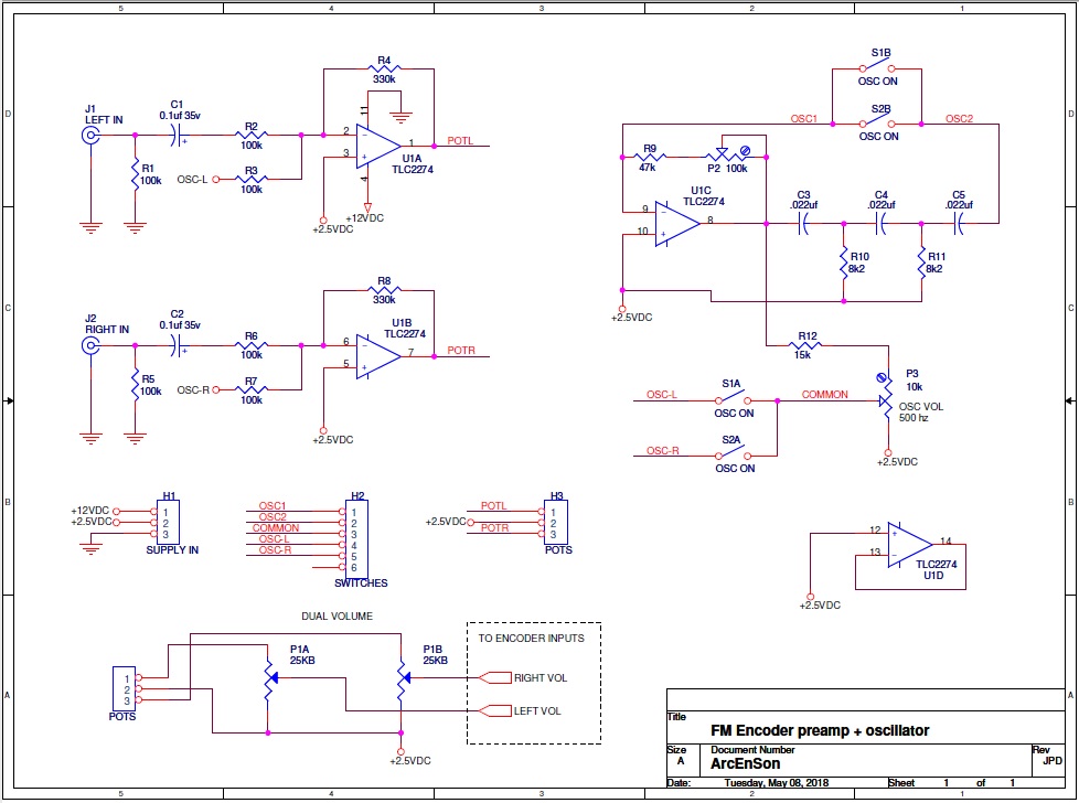
Frontend circuit
that amplifies the external audio and add 500hz tones
So I started to build both PCB’s and test them all
connected together.
After some tests I decided to remove both R31,38 2k ohms PIRA’s
Input resistors and replaced them with 10k ohms to
ease my two TLC2274
Opamps from driving
too much current to the PIRA’s inputs.
Doing so I also replaced C22,23 for 10uf capacitors
instead of 220uf.
Now I have plenty of gain on the external audio
inputs
AND I can use separate L-R 500hz tones for further
tests.
All of these are finally connected to my Marconi 2022E
external modulation input.
The
project’s final steps..
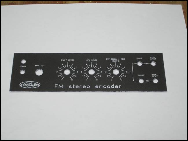
First, I started to draw the front panel layout and
placed
All the components that would be useful:
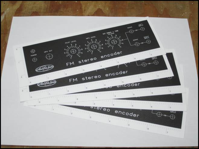
I used Front Designer software to make the layout.
This soft is amazing to get things done quick !
I could place 5 of my layout on the same page.
I printed them on a self-adhesive laminated vinyl for easy
application on the front metal plate.
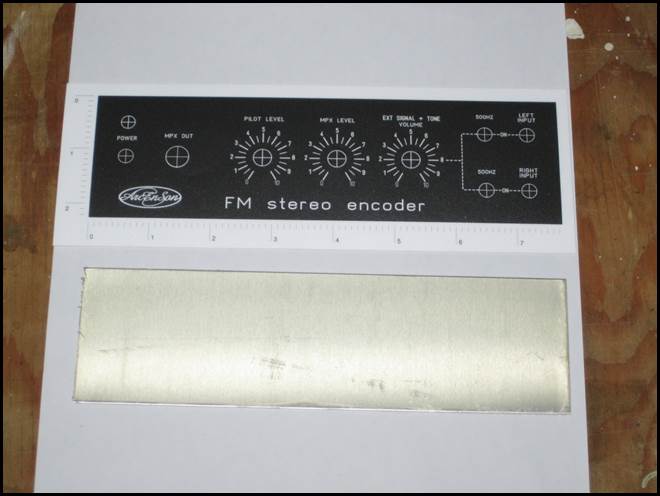
After sticking the layout on the bare metal plate
I used my bench punch press to punch all the holes
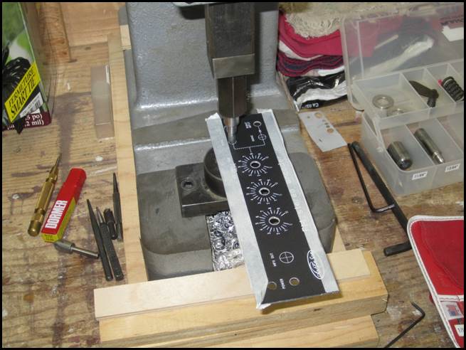
This gave this result (no drills residues)
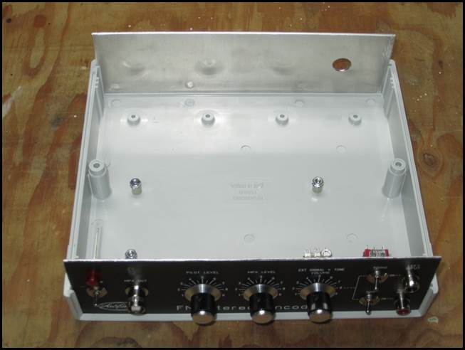
I used a Hammond 1598D plastic cabinet
to place all my project stuff..
I then Placed the pots, switches, RCA connectors,
etc..
I then placed all the assembled PCB’s with the
wirings.
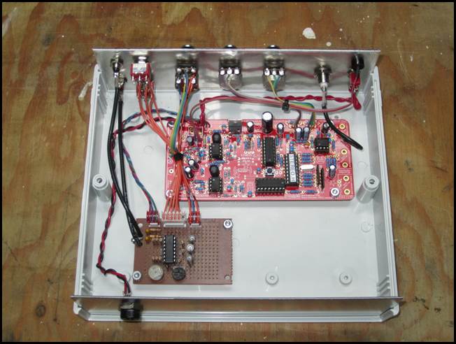
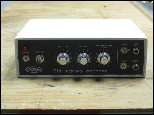
The final assembly looks like this
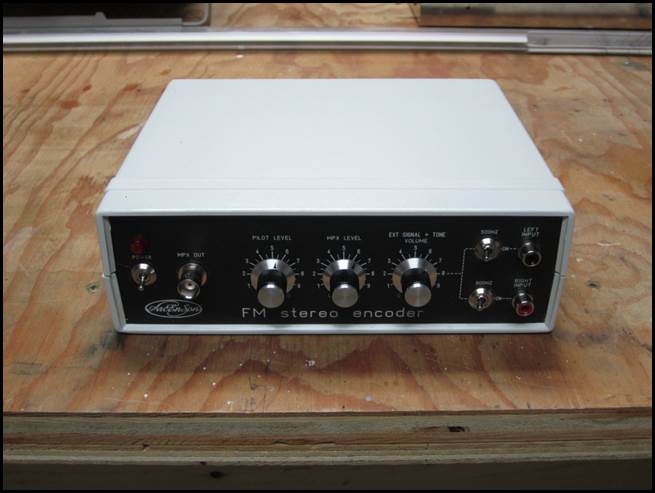
Thank you for your time and for having interest for
this project !
If you’d like to have a look at some of my other
projects
Just go to www.arcenson.com/projects

info@arcenson.com
2018